Apparatus and method for controlled laser heating

Inactive Publication Date: 2015-12-03
FRACTURELAB
View PDF25 Cites 7 Cited by
  • Summary
  • Abstract
  • Description
  • Claims
  • Application Information

AI Technical Summary

Benefits of technology

[0022]In one such configuration, the integrating chamber is of a substantially teardrop-like shape, with the geometry of the cusp of the teardrop truncated or similarly modified to accommodate the chamber opening, thereby permitting improved access into fillets or depressions in the surface of the body.
[0023]In a further variant, the interior surface of a teardrop-shaped integrating chamber is of a terraced configuration in the vicinity of the (albeit truncated) cusp of the teardrop, thereby more efficiently reflecting light back into the more spherical portion o

Problems solved by technology

Too much or too little energy imparted to the process can negatively impact process quality.
However, because of material variability, especially with regard to the reflectivity of the material, the actual thermal profile, phase changes, and other parameters resulting from a process so prescribed will in fact vary, with potential for process failure or poor quality.
However, using this method, the amount of energ

Method used


Image

  • Apparatus and method for controlled laser heating
  • Apparatus and method for controlled laser heating
  • Apparatus and method for controlled laser heating

Examples


Embodiment Construction

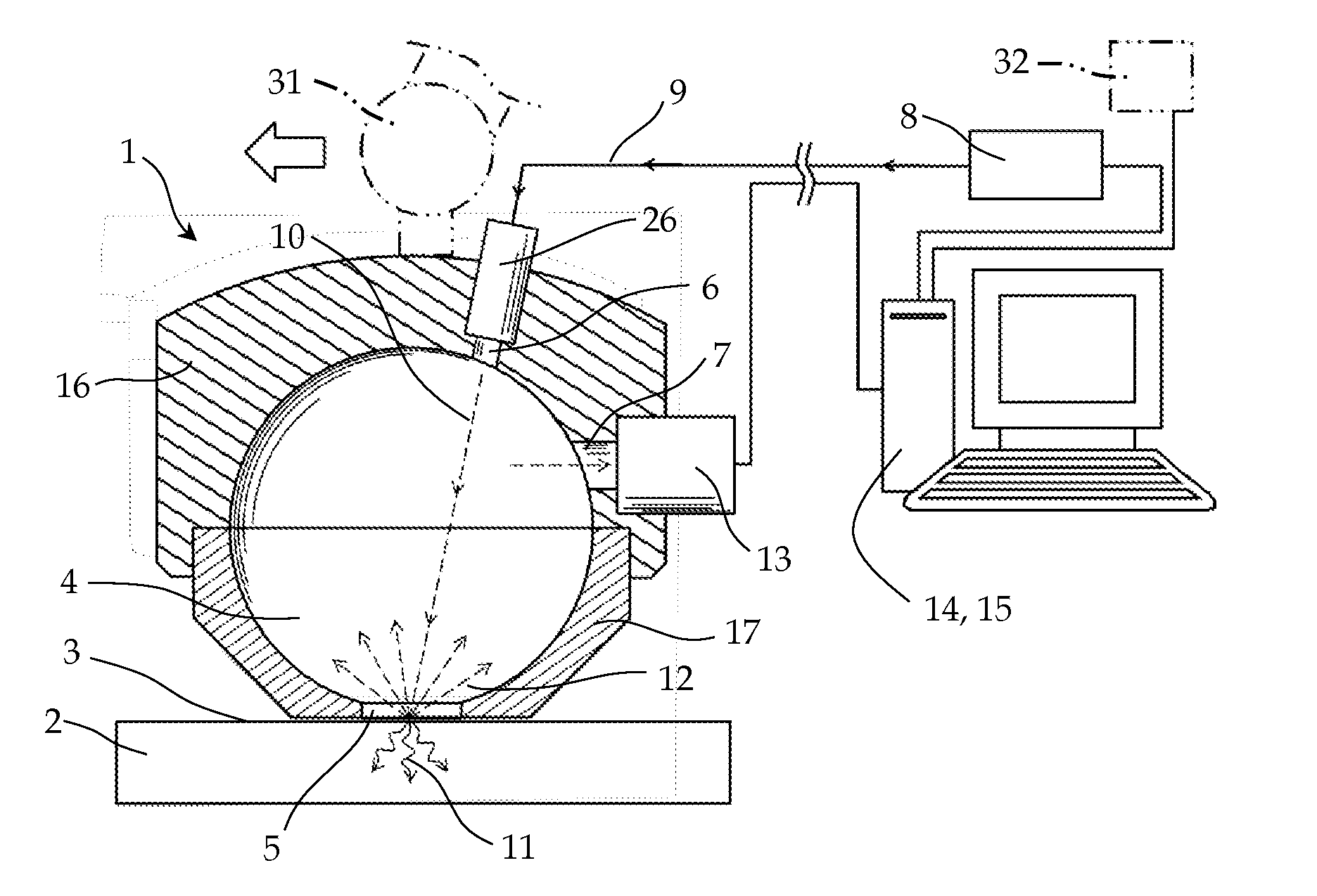
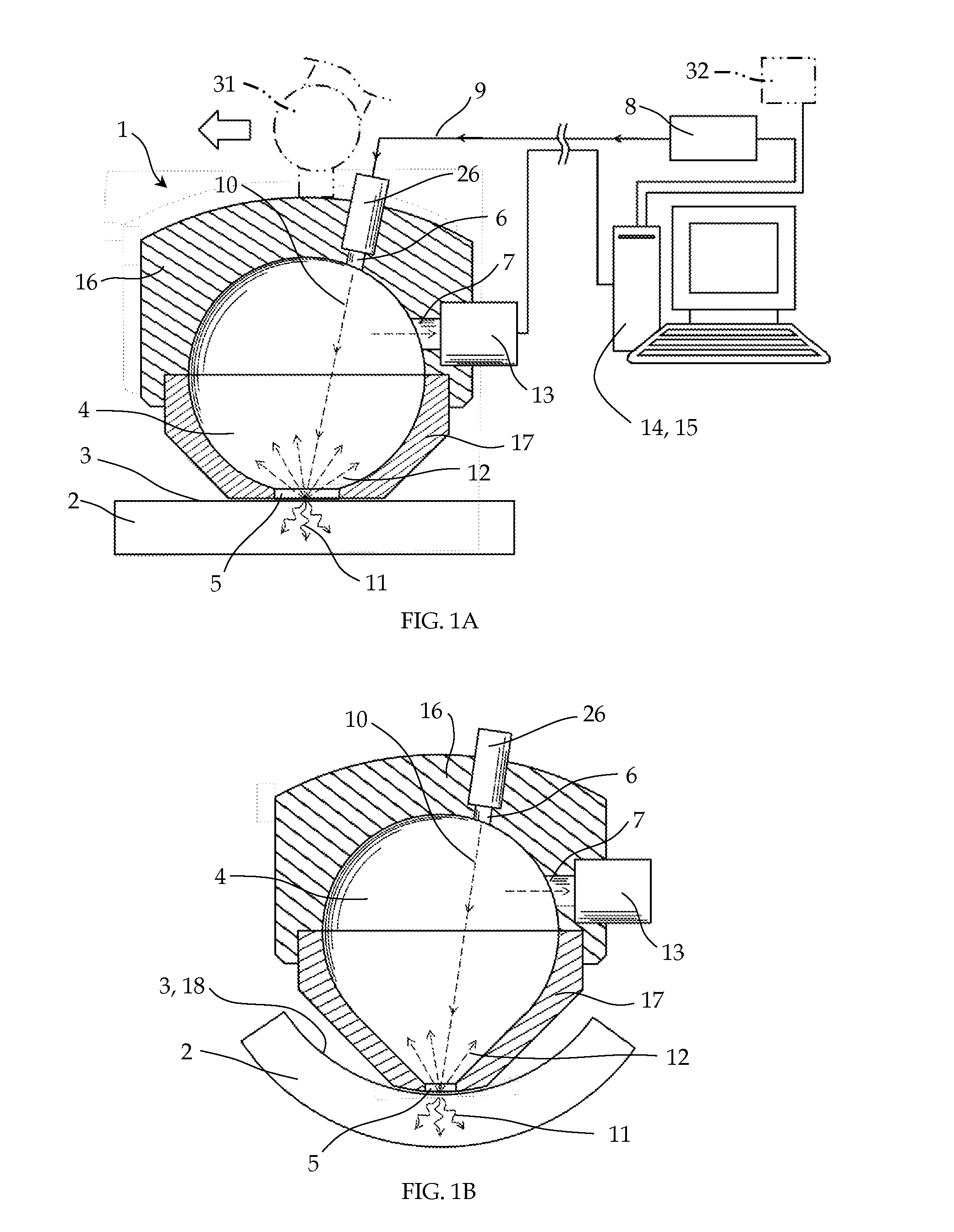
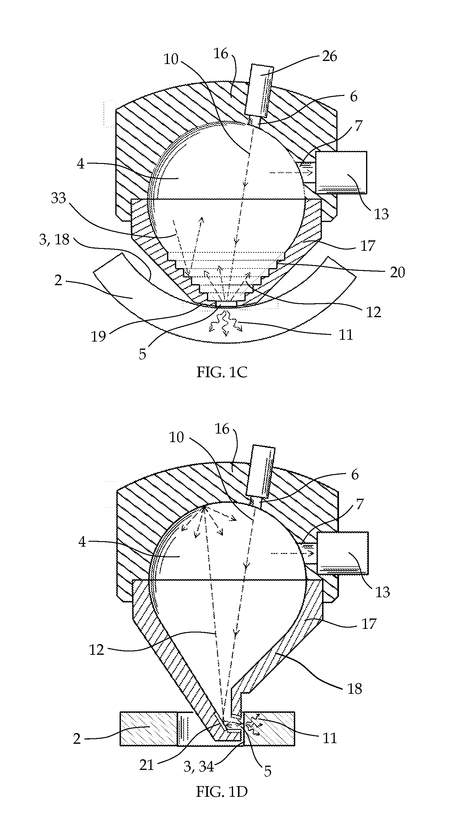
[0039]FIG. 1A, shows a schematic representation of an apparatus 1 for controlled laser heating of a body 2, including a body 2 having a surface 3, an optical integrating chamber 4, with an opening 5 adjacent to the surface 3 of the body 2, and a first aperture 6 and second aperture 7. A laser source 8, produces a beam 10 of known power which is directed through the first aperture 6 and the chamber opening 5 onto the surface 3. For illustration, the beam is carried to the chamber by a fiber optic cable 9, which is mounted to the chamber wall 16 by attachment 26. A portion 11 of the power of the laser beam 10 is absorbed by the body, thereby heating it locally, and the remaining portion 12 is substantially reflected back into the chamber 4.

[0040]A photodetector 13 samples the reflected light accumulated within the chamber 4 through the second aperture 7, thereby discerning the total power of the reflected light 12, and enabling the computation of the absorbed power 11 imparted as heat...


PUM

PropertyMeasurementUnit
Fractionaaaaaaaaaa
Poweraaaaaaaaaa
Surfaceaaaaaaaaaa

Abstract

The invention pertains to an apparatus and method for controlled laser heating of a body. An optical integrating chamber, with an opening adjacent to the surface of the body, has a first and second aperture. A laser source, produces a beam of known power which is directed through the first aperture and the chamber opening onto the surface. A portion of the power of the laser beam is absorbed by the body, thereby heating it locally, and the remaining portion is substantially reflected back into the chamber. A photodetector samples the reflected light accumulated within the chamber through the second aperture, thereby discerning the total power of the reflected light, and enabling the computation of the absorbed power imparted as heat to the body. This computation is performed by a computer or controller, which also serves as a control feedback mechanism, by which the application of the laser is controlled based on the absorbed power imparted to the body during the heating process. Several embodiments are described, useful for a wide range of potential applications in processing and evaluation of organic and inorganic materials and structures.

Description

CROSS-REFERENCE TO RELATED APPLICATIONS[0001]Not Applicable.BACKGROUND OF THE INVENTION[0002]1. Field of the Invention[0003]The invention pertains to an apparatus and method for controlled laser heating of a substantially solid body. Potential uses include any application which would benefit from the ability to quantify or prescribe the amount of laser power or energy actually imparted to and absorbed within the body, thus including but not limited to laser processing of inorganic materials, such as metals and ceramics, laser processing of organic materials or tissues, including laser surgery, and local laser interrogation of materials to evaluate material properties or damage. Many potential applications will be apparent to one skilled in the art in light of the description of exemplary embodiments that will be given hereafter.[0004]2. Description of the Prior Art[0005]The use of a laser as a heat source is broadly used in many industries, and is finding new applications at an acce...

Claims


Application Information

Patent Timeline
IPC IPC(8): B23K26/03B23K26/12G01N21/88A61B18/20C21D1/34G01N21/55B23K26/00B23K26/06
CPCB23K26/032B23K26/0069B23K26/128B23K26/0626A61B18/20G01N2021/555G01N21/55G01N21/8806A61B2018/00714G01N2201/06113C21D1/34B23K26/0006B23K26/0884B23K26/12B23K26/1464A61B2017/0007A61B2018/00642A61B2018/00785A61B2018/00809B23K26/0622B23K26/352C21D10/005C21D1/09B23K2103/30B23K2103/32B23K2103/52G01K17/003
Inventor PETTIT, RICHARD G.SINGH, RIPUDAMAN
Owner FRACTURELAB
Why Eureka
Try Eureka