Absorbance monitor

a technology of absorbance monitor and absorbance beam, which is applied in the direction of optical radiation measurement, color/spectral property measurement, instruments, etc., can solve the problems of measurement error, linearity degradation, and different temperature characteristics, so as to achieve the effect of effectively utilizing the wavelength characteristics of reflected light on the optical elemen

Active Publication Date: 2005-04-21
HORIBA LTD
View PDF4 Cites 8 Cited by
  • Summary
  • Abstract
  • Description
  • Claims
  • Application Information

AI Technical Summary

Benefits of technology

[0016] In the absorbance monitor described above, the light collecting member lies preferably between the light source and the sample cell. The present inventors found that the technical effect described above is more effective under conditions where the quantify of light from the light guiding opening is scarcely attenuated, and the light collecting member is arranged preferably adjacently to a light path having a large quantity of light with many angular components, that is, adjacently to a light source, so that the attenuation of reflected light on a light path-forming surface such a wall of a sample cell does not occur.
[0017] Further, an optical element used for another detector described above is arranged preferably in the light guiding opening and adjacently to a light path formed by the light collecting member. By this arrangement, an optical loss by the light guiding opening arranged on a part of the light path in the optical system can be reduced, and the wavelength characteristics of reflected light on the optical element can be effectively utilized.

Problems solved by technology

In a sample containing a plurality of components, however, the respective components are often significantly different in concentration from one another, and the absorbance monitors described above in the related art may cause the following problems.
One problem lies in measurement errors caused generally by a relationship similar to light absorption characteristics called the Lambert-Beer law expressed in the following equation (1), between the quantity of light absorbed (that is, the concentration of component to be measured) and detector output.
That is, in the optical system using one sample cell, the quantity of light absorbed is significantly varied depending on the intended component so that when a low-concentration sample is measured, an output region of good linearity can be utilized, while when a high-concentration component is measured, the linearity of output is deteriorated, thus causing a difference in reading miscalculation and a difference in temperature characteristics.
Accordingly, to or more optical systems different in cell length are often used in one analyzer, resulting enlargement of the analyzer.
So due to optical loss caused by a larger size of the optical system and an addition of the part, there may arise a problem of deterioration in detection sensitivity.
For the purpose of reducing a sample flow in the optical system described above, the aperture diameter of the sample cell may be decreased, but the same problem may also arise in this case.
Specifically, there is an optical system wherein a light collecting member 5 or a sample cell 2b is additionally used as shown in FIG. 9, but there may arise a problem of deterioration in detection sensitivity due to optical loss caused by addition of the part.

Method used


Image

  • Absorbance monitor
  • Absorbance monitor
  • Absorbance monitor

Examples


Embodiment Construction

[0027] Hereinafter, embodiments of the invention are described in detail.

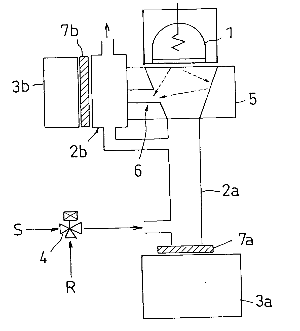
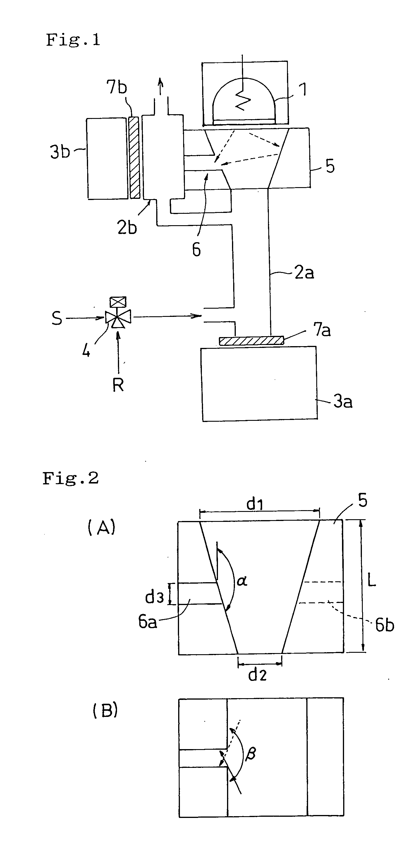
[0028]FIG. 1 shows a first constitutional example of the absorbance monitor of the present invention. In FIG. 1, an optical system is formed from a light path comprising a light source 1 receiving electric power from an electric source (not shown), a light collecting member 5, a sample cell 2a, an optical element 7a and a detector 3a, and a light path having a light guiding path 6 via a part of an inside wall of the light collecting member 5, a sample cell 2b, an optical element 7b and a detector 3b. A fluid is introduced from the sample cell 2a into the sample cell 2b, where a sample fluid S and a reference fluid R are switched periodically with each other using a fluid switch 4, whereby a change in the amount of absorbed infrared ray in each of the sample cells 2a and 2b can be taken out as an alternating current signal by each of the detectors 3a and 3b (fluid modulation). As described above, each detector ...


PUM

PropertyMeasurementUnit
angleaaaaaaaaaa
wavelengthaaaaaaaaaa

Abstract

This invention relates to a multi-component absorbance monitor, and the object is to provide a general-purpose and highly accurate compact absorbance monitor. Disclosed is an absorbance monitor including a light source, a sample cell and a plurality of detectors as elements, wherein a light collecting member is arranged between the light source and one detector, and an inside wall of the light collecting member has a site for guiding a part of light from the light source, that is, a light guiding opening, and light from the light guiding opening enters another detector. Preferably, the light collecting member lies between the light source and the sample cell. Preferably, an optical element used for another detector described above is arranged in the light guiding opening and adjacently to a light path formed by the light collecting member.

Description

BACKGROUND OF THE INVENTION [0001] 1. Field of the Invention [0002] The present invention relates to an absorbance monitor for measuring the concentrations of specific components in various fluids and is particularly useful in a highly accurate and compact fluid concentration measuring instrument for measuring a plurality of components present in a sample. [0003] 2. Description of the Related Art [0004] In various production processes in recent years, it is essential to control the concentrations of substances controlled and various interfering substances, and highly accurate measuring instruments capable of coping with various uses are required. Conventionally, general-purpose absorbance monitors capable of measuring many kinds of components simultaneously in the same constitution, such as a non-dispersive infrared analyzer (referred to hereinafter as “NDIR”) and a non-dispersive ultraviolet analyzer (referred to hereinafter as “NDUV”), are often used. Such absorbance monitors do b...

Claims


Application Information

Patent Timeline
Patent Type & Authority Applications(United States)
IPC IPC(8): G01J5/02G01N21/00G01N21/01G01N21/05G01N21/27G01N21/31G01N21/37G01N21/61G01N35/02
CPCG01N21/05G01N21/3504G01N21/276
Inventor OIDA, TAKUJIAKIYAMA, SHIGEYUKIENDO, MASAHIKOIWATA, NORIKAZUINOUE, SATOSHIFUJIWARA, MASAHIKO
Owner HORIBA LTD
Why Eureka
Try Eureka