Blind spot detection module

a detection module and blind spot technology, applied in the field of blind spot detection system, can solve the problemsaffecting the thickness of instruments, and affecting the quality of optical patterns, so as to achieve the effect of reducing light efficiency, maximizing light efficiency, and thinning instruments

Active Publication Date: 2015-11-19
LG INNOTEK CO LTD
View PDF22 Cites 4 Cited by
  • Summary
  • Abstract
  • Description
  • Claims
  • Application Information

AI Technical Summary

Benefits of technology

[0015]According to an embodiment of the present invention, in a blind spot detection module, a structure of a light source for applying light to a warning optical pattern formed in a reflective mirror is formed in a structure in which the light source emits light by applying a resin so that thinning of an instrument can be realized, and light efficiency can be maximized.
[0016]In particular, thanks to flexibility of a resin material and thinning of a light guide structure, a design for utilizing a space can be diversified, and thanks to high light efficiency, luminance for enabling a warning optical pattern to be observed even in the daytime as well as at night can be implemented so that visibility can be improved. Also, since the number of light sources is reduced, very high luminance can be implemented compared to the number of light sources.
[0017]Also, according to another embodiment of the present invention, light is guided using a resin material having flexibility so that the number of light emitting packages can be reduced, an entire thickness of a surface lighting device can be thinner, and the degree of freedom in design of the product can be increased.
[0018]Furthermore, an optical pattern layer is formed in a light source module according to the present invention so that occurrence of the concentration of light and a hot spot can be prevented, the uniformity of light supplied to a diffusion plate can be improved, and luminance of a desired place can be adjusted by adjusting a path of light.
[0019]Also, since a reflection member and light shielding patterns are formed in the same color upon implementing a light source module according to still another embodiment of the present invention so that a lamp before emission can have a mirror-like shape, and a reflection sheet and a reflection pattern, which are structures capable of efficiently reflecting light emitted from a light emitting unit, are provided so that the reflectance of light can be improved, the improvement of luminous can be maximized, and a uniform surface light source can be provided.
[0020]Also, according to still another embodiment of the present invention, a light guide layer having protruding optical patterns is provided between a light guide member and a reflection member so that the shape and the three-dimensional effect of light can be changed according to each viewing angle, and an adhesive pattern is formed between the light guide layer and the reflection member so that the shape of geometrical optical patterns can be changed, a light source module having improved aesthetic sensibility can be provided, and application for various kinds of light source modules can be realized.

Problems solved by technology

Thus, there are many limitations in forming a thickness of the entire instrument because such a space should be secured.
Thus, since uniformity of the light cannot be secured, it is problematic in that uniform light may not be appropriately provided to the optical patterns.
In particular, it is problematic in that light efficiency is remarkably reduced because merely reflection light is implemented due to a very large inner space of the reflective instrument 20.

Method used


Image

  • Blind spot detection module
  • Blind spot detection module
  • Blind spot detection module

Examples


first embodiment

1. First Embodiment

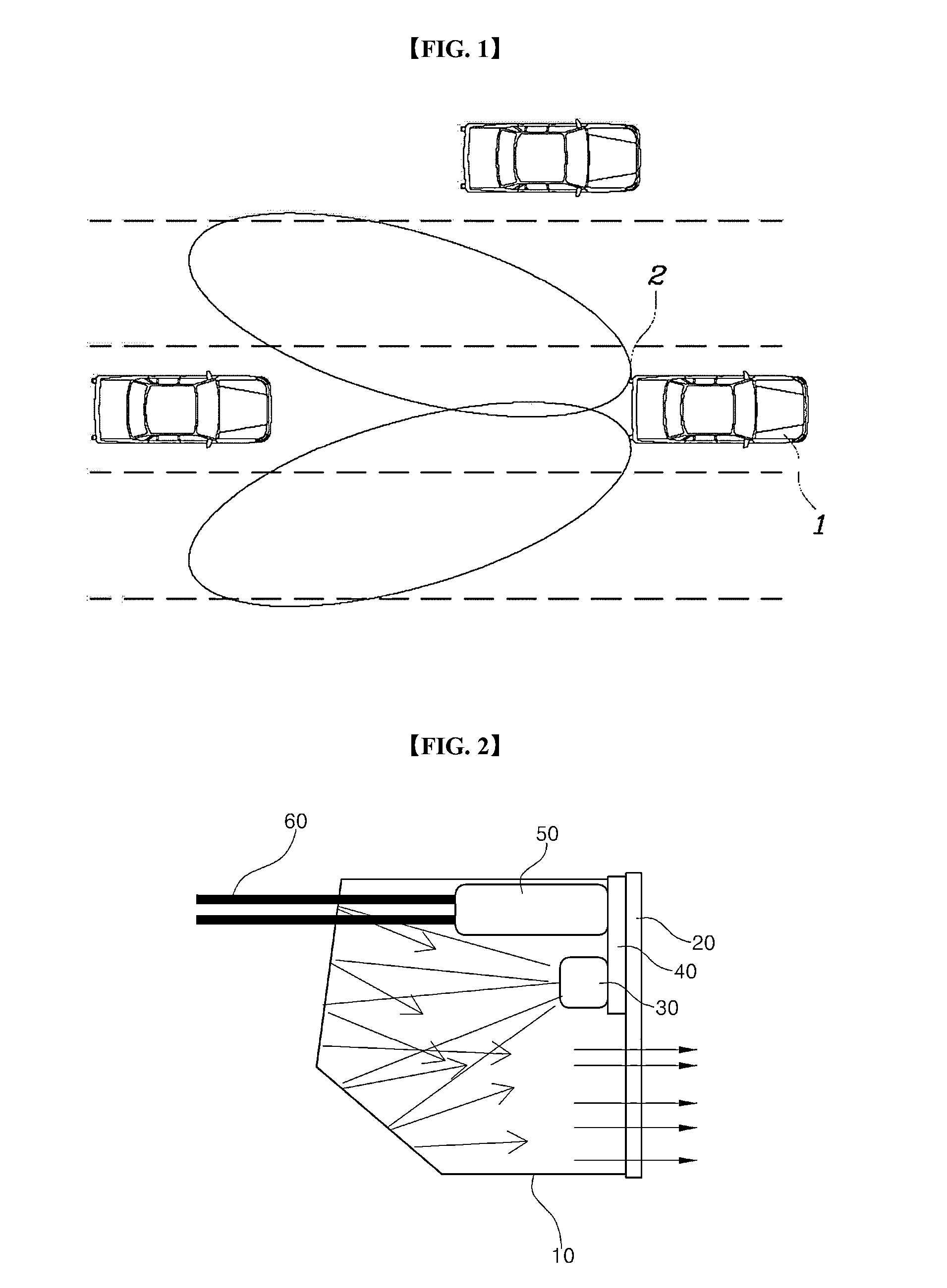
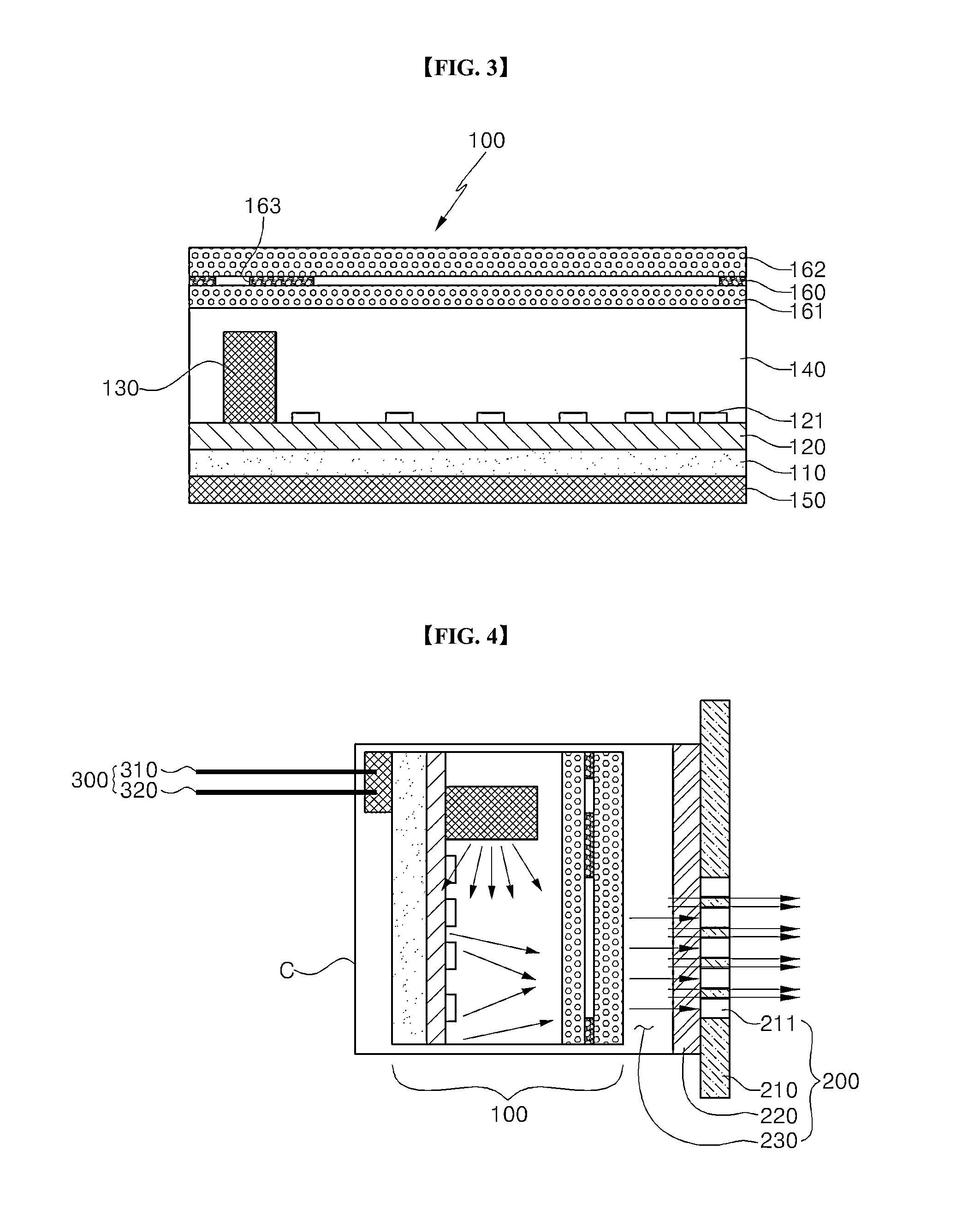
[0048]FIG. 3 is a conceptual view of a cross section illustrating the subject matter of a light source module of a blind spot detection module according to the present invention, and FIG. 4 is a conceptual view of a cross section illustrating a structure of the blind spot detection module according to the present invention including the light source module of FIG. 3.

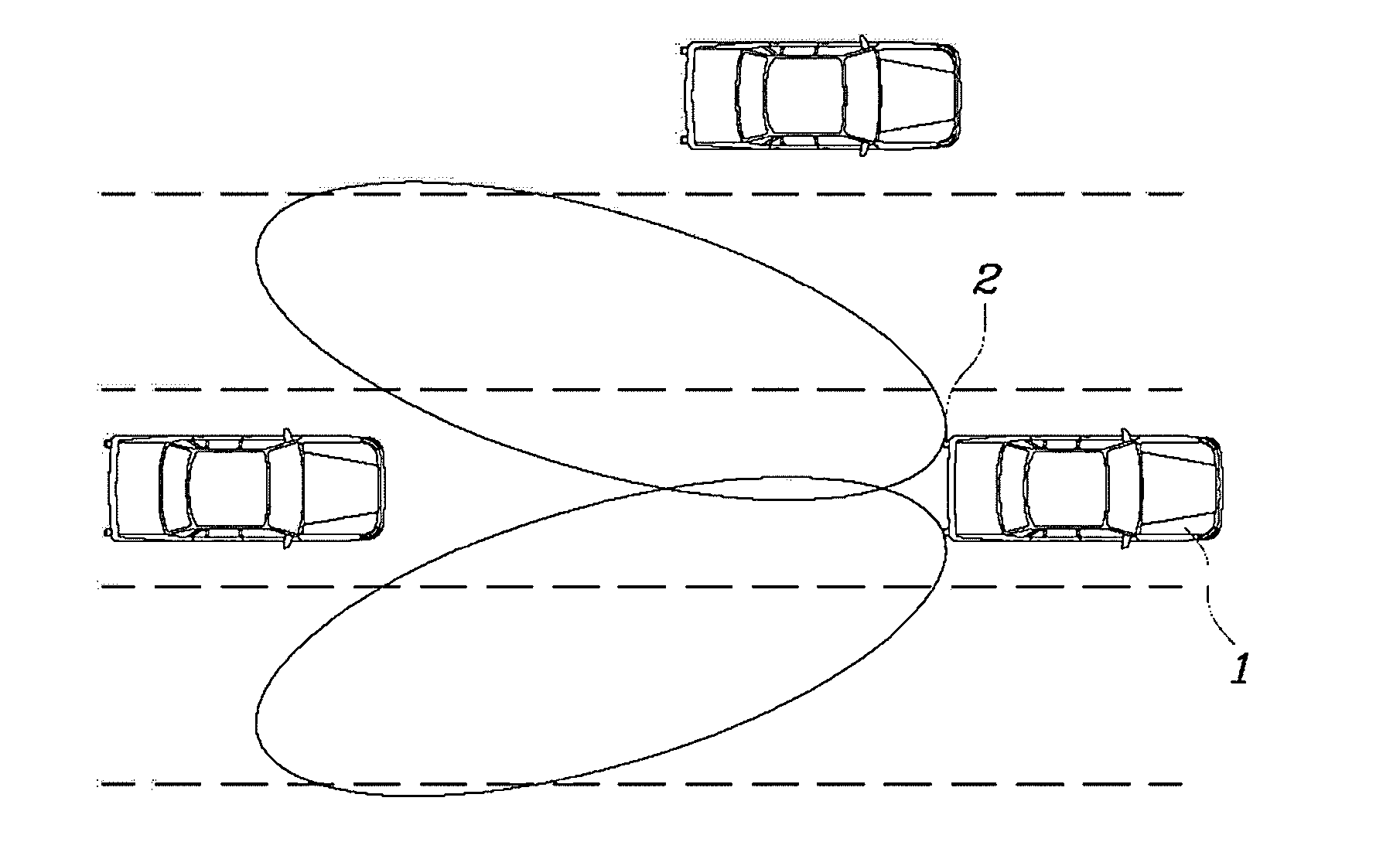
[0049]Referring to FIGS. 3 and 4, a blind spot detection module according to the present invention includes: a light source module 100 linked with a sensor signal for the detection of an object in a rear side area of a vehicle to emit light; and a reflector module 200 including a warning optical pattern 211 transmitting light emitted from the light source module 100.

[0050]In particular, the light source module 100 according to the present invention includes a light guide member 140 adopted to receive a light emitting element 130 and to guide light to the reflector module 200. In particular, the light g...

second embodiment

2. Second Embodiment

[0075]FIGS. 5 to 7 illustrate modified embodiments in which the structure of FIG. 4 is modified.

[0076]The structure of the blind spot detection module illustrated in FIG. 5 is implemented such that the reflection pattern 121 in the light source module is omitted from the configuration of the blind spot detection module according to the embodiment of the present invention of FIG. 4. In the structure, a thickness of the resin material layer may be adjusted, and illustrated optical pattern layers may be also removed according to circumstances so that luminance can be improved.

[0077]Furthermore, the structure of the blind spot detection module illustrated in FIG. 6 may be implemented such that the diffusion member 210 of the reflector module 200 is removed from the structures of FIGS. 3 and 4. In the structure, the reflection pattern in the light source module is visible from the warning optical pattern 211 in the reflector. Thus, the structure of FIG. 6 may be imple...

third embodiment

3. Third Embodiment

[0080]Hereinafter, the other embodiment in which the structure of the light source module applied to the first and second embodiments is modified will be described.

[0081]Even though the third embodiment is similar to the first and second embodiments with respect to the basic structure of the light source module for implementing surface light emission, the light source module applied to the third embodiment may implement a mirror effect by forming a reflection member and optical patterns included in the light source module in the same color. Furthermore, a light guide layer composed of a light guide member and having protruding optical patterns is formed between the light guide member and the reflection member, so that the light source module capable of implementing a three-dimensional geometric effect has been suggested.

[0082]Referring to FIG. 4, the light source module according to the present invention may further include: a printed circuit board 110; at least o...


PUM


Abstract

Provided is a blind spot detection module, including: a light source module linked with a sensor signal for detection of an object in an area behind a vehicle to emit light; and a reflector module including a warning optical pattern for transmitting light emitted from the light source module, wherein the light source module comprises a light guide member adopted to receive a light emitting element and to guide light to the reflector module.

Description

TECHNICAL FIELD[0001]Embodiments of the present invention relate to a blind spot detection system, and more particularly, to a technology for implementing thinning, design efficiency, and the maximization of light efficiency of a blind spot detection module changing a monitoring area in blind spot according to each driving state of a vehicle.BACKGROUND ART[0002]In general, a blind spot detection system is a system intended to increase convenience of a driver by giving the driver a warning when an obstacle is found in the dead angle area of a rear side of a vehicle during driving, or when there is the risk of colliding with an obstruct in a blind zone upon the lane change of a vehicle or the risk of collision resulting from a lane change of another vehicle that approaches the vehicle at high speed from a rear side of left and right seats.[0003]As illustrated in FIG. 1, the blind spot detection system has a sensor 2 installed at a rear side of a vehicle 1, wherein the sensor 2 detects...

Claims


Application Information

Patent Timeline
Patent Type & Authority Applications(United States)
IPC IPC(8): B60Q9/00F21W107/10
CPCB60R2300/802B60Q9/008B60R1/12B60R2001/1215G02B6/0036G02B6/0041
Inventor PARK, MOO RYONGKIM, JIN HEELEE, BYOUNG EONYANG, HYUN DUCKPARK, KWANG HO
Owner LG INNOTEK CO LTD
Why Eureka
Try Eureka