Optical pickup apparatus

a pickup apparatus and optical technology, applied in the field of optical pickup apparatuses, can solve problems such as adverse effects on tracking error signals, and achieve the effect of effectively utilizing reflected light and suppressing adverse effects

Inactive Publication Date: 2008-08-28
SHARP KK
View PDF4 Cites 5 Cited by
  • Summary
  • Abstract
  • Description
  • Claims
  • Application Information

AI Technical Summary

Benefits of technology

[0045]According to the invention, the light emitted from the light source is split into a main light beam and a sub light beam by the splitting portion. The main light beam has a high light intensity, whereas the sub light beam has a low light intensity. Accordingly, the adverse effects caused by the first-order diffraction light of the main light beam from the non-light-collecting recording layer are large, whereas the adverse effects caused by the first-order diffraction light of the sub light beam from the non-light-collecting recording layer are small.
[0046]In view of this point, the second diffraction region is disposed so that the first-order diffraction light of the main light beam from the non-light-collecting recording layer enters thereon. As a result, it is possible to effectively suppress the adverse effects caused by the reflected light from the non-light-collecting recording layer. In addition, the first diffraction region and the second diffraction region are disposed so that the part of the first-order diffraction light of the sub light beam from the non-light-collecting recording layer deviates from the second diffraction region and enters on the first diffraction region. Consequently, it is possible to effectively utilize the reflected light from the light-collecting recording layer, by making the first diffraction region as large as possible so that the reflected light from the light-collecting recording layer is diffracted by the first diffraction region as much as possible.

Problems solved by technology

As a result, this causes a problem of adverse effects on the tracking error signal.

Method used


Image

  • Optical pickup apparatus
  • Optical pickup apparatus
  • Optical pickup apparatus

Examples


first embodiment

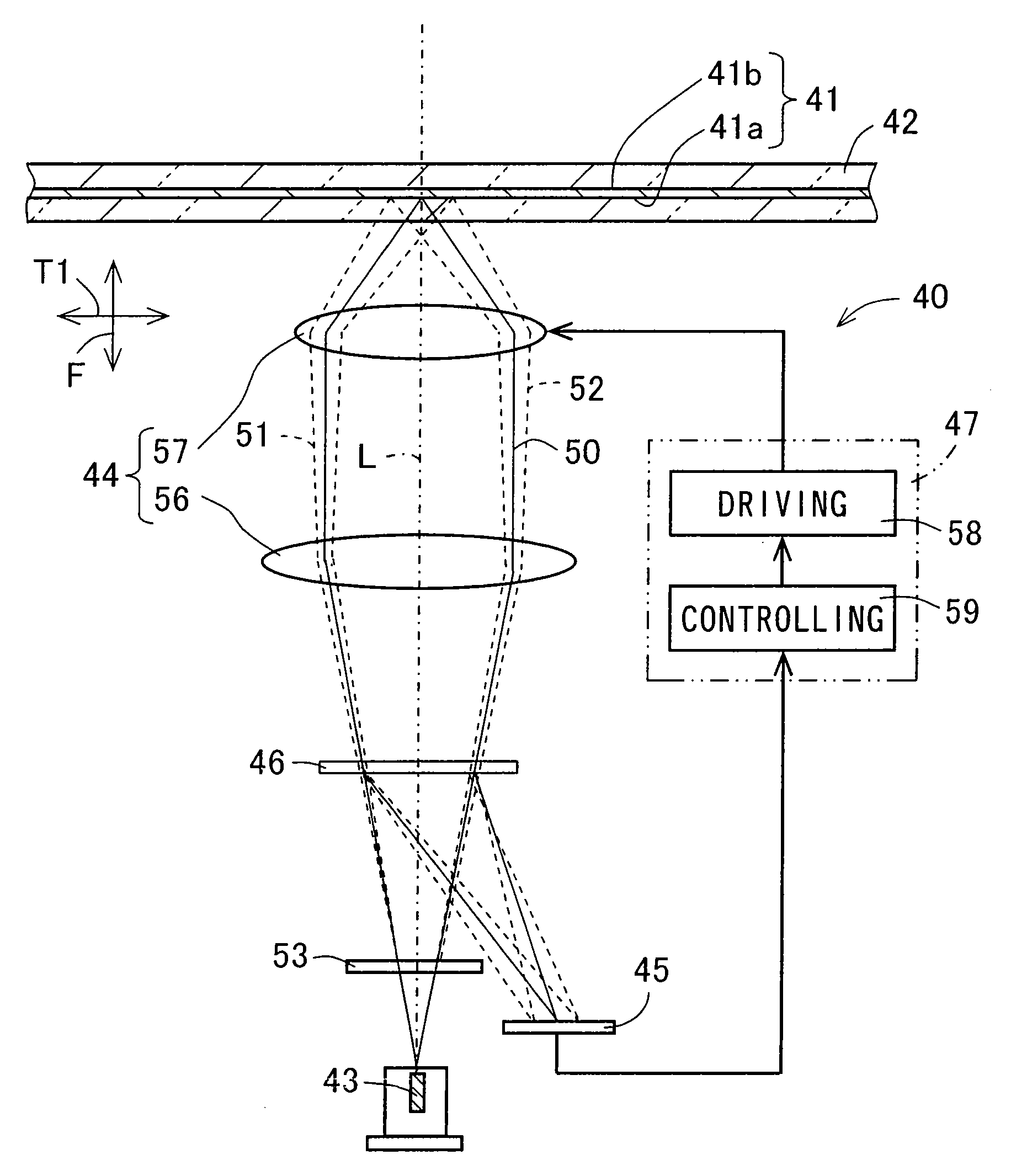
[0064]FIG. 1 is a view schematically showing a configuration of an optical pickup apparatus 40 according to the invention. The optical pickup apparatus 40 according to the embodiment is used for irradiating an optical disc 42 having a plurality of recording layers 41 with light from one side of the optical disc 42 so as to record information on the recording layers 41 of the optical disc 42 or reproduce the information from the optical disc 42.

[0065]The optical disc 42 is an optical recording medium. The respective recording layers of the optical disc 42 are laminated in a thickness direction of the optical disc 42. The recording layer 41 of the reproduction-only optical disc 42 has spirally formed pit rows, and a track is formed by the pit rows. In such a reproduction-only optical disc 42 as mentioned above, information is represented by the pits. The recording layer 41 of the record-only optical disc 42 has spirally formed lands and grooves, and the track is formed by the lands an...

third embodiment

[0138]In the embodiment, the first diffraction region has the first to the fourth TES diffracting portions 71 to 74, and the second diffraction region has an FES diffracting portion 70B. The FES diffracting portion 70B is so formed as to include the FES diffracting portion 70, and the second and the third FES diffracting portions 81A and 82A in the above-described

[0139]In such an embodiment as has been described, the FES diffracting portion 70B includes the region 91 on which the zero-order diffraction light from the non-light-collecting recording layer 41b enters, and the regions 93 and 94 on which the first-order diffraction lights from the non-light-collecting recording layer 41b enter. It is possible to reduce number of dividing the diffracting portion 46B by configuring the FES diffracting portion 70B in the above-mentioned way. Accordingly, it is possible to decrease number of manufacturing steps of the diffracting portion 46B, thus making it possible to reduce manufacturing c...


PUM

PropertyMeasurementUnit
red wavelengthaaaaaaaaaa
depthaaaaaaaaaa
thicknessaaaaaaaaaa

Abstract

A diffracting portion is disposed in an optical path between a light source and an optical disc. The diffracting portion diffracts the reflected light from recording layers of the optical disc toward a light receiving portion. The diffracting portion includes a first diffraction region having a first diffraction efficiency and a second diffraction region having a second diffraction efficiency lower than the first diffraction efficiency. The first diffraction region includes a FES diffracting portion and first to fourth TES diffracting portions. The second diffraction region includes fifth and sixth TES diffracting portions. First-order diffraction lights from the non-light-collecting recording layer enter on the fifth and the sixth TES diffracting portions, and are diffracted toward the light receiving portion by the fifth and the sixth TES diffracting portions.

Description

CROSS-REFERENCE TO RELATED APPLICATION[0001]This application claims priority to Japanese Patent Application No. 2007-046130, which was filed on Feb. 26, 2007, the contents of which are incorporated herein by reference in its entirety.BACKGROUND OF THE INVENTION[0002]1. Field of the Invention[0003]The present invention relates to an optical pickup apparatus for recording information on an optical recording medium or reproducing information from an optical recording medium.[0004]2. Description of the Related Art[0005]FIG. 13 is a view schematically showing a configuration of a conventional optical pickup apparatus 1. An optical disc 7 serving as an optical recording medium has a recording layer 8. When information is recorded and / or reproduced on and from such an optical disc 7, laser light is collected on the recording layer 8 of the optical disc 7 and the recording layer 8 is irradiated therewith, and then reflected light from the optical disc 7 is received by a light receiving port...

Claims


Application Information

Patent Timeline
Patent Type & Authority Applications(United States)
IPC IPC(8): G11B7/00
CPCG11B7/0906G11B7/0912G11B7/0916G11B2007/0013G11B7/1353G11B7/1381G11B7/131
Inventor MATSUBARA, KAZUNORIMURAKAMI, SHINZOH
Owner SHARP KK
Why Eureka
Try Eureka