Plug locking device

a locking device and plug technology, applied in the direction of coupling device connection, engine-driven generator propulsion, transportation and packaging, etc., can solve the problems of wrongly removing the power feeding plug, complicated bolt fastening of the bolt 106 from the inner side of the vehicle, and vehicle may be left unattended

Inactive Publication Date: 2013-01-22
KK TOKAI RIKA DENKI SEISAKUSHO
View PDF3 Cites 33 Cited by
  • Summary
  • Abstract
  • Description
  • Claims
  • Application Information

AI Technical Summary

Benefits of technology

[0009]A further aspect of the present invention is a locking device for use with an inlet including a plug port, which receives a power feeding plug, and a base, which includes a bolt hole. The locking device locks a hook of the power feeding plug in a state in which the hook is engaged with an outer surface of the plug port to restrict removal of the power feeding plug from the inlet. The locking device includes a housing having a frame, which receives the plug port, and a hook port, which receives the hook. A movable member moves between a lock position, in which the movable member is arranged inside the hook port, and an unlock position, in which the movable member is arranged outside the hook port. The movable member, when located at the lock position, locks the hook in a state in which the hook is engaged with the outer surface of the plug port. A controller moves the movable member to the lock position when the plug port receives the power feeding plug. The housing is fastened to the base to hide a fastening bolt, which is inserted into the bolt hole. When the plug port receives the power feeding plug and the movable member is located at the lock position, the movable member contacts the hook port and the hook, which is engaged with the outer surface of the plug port, to restrict removal of the housing from the base.
[0010]Another aspect of the present invention is a power supplying system including a power feeding plug having a hook. An inlet includes a plug port, which receives the power feeding plug, and a base, which includes a bolt hole. A locking device is fastened to the base of the inlet. The locking device locks the hook of the power feeding plug in a state in which the hook is engaged with an outer surface of the plug port to restrict removal of the power feeding plug from the inlet. The locking device includes a housing having a frame, which receives the plug port, and a hook port, which receives the hook. The frame has an inner dimension that is smaller than an outer dimension of the power feeding plug. A movable member moves between a lock position, in which the movable member is arranged inside the hook port, and an unlock position, in which the movable member is arranged outside the hook port. The movable member, when located at the lock position, locks the hook in a state in which the hook is engaged with the outer surface of the plug port. A controller moves the movable member to the lock position when the plug port receives the power feeding plug. The housing is fastened to the base to hide a fastening bolt, which is inserted into the bolt hole. When the plug port receives the power feeding plug and the movable member is located at the lock position, the movable member contacts the hook port and the hook, which is engaged with the outer surface of the plug port, to restrict removal of the housing from the base.

Problems solved by technology

As a result, the vehicle may be left unattended over a long period of time with the power feeding plug connected to the inlet of the vehicle.
In such a case, someone may wrongfully remove the power feeding plug and connect it to another vehicle to steal electricity or steal the power feeding plug.
However, the fastening of the bolts 106 from the inner side of the vehicle would be complicated.

Method used


Image

  • Plug locking device
  • Plug locking device
  • Plug locking device

Examples


Embodiment Construction

[0021]A locking device for a power feeding plug according to one embodiment of the present invention will now be described.

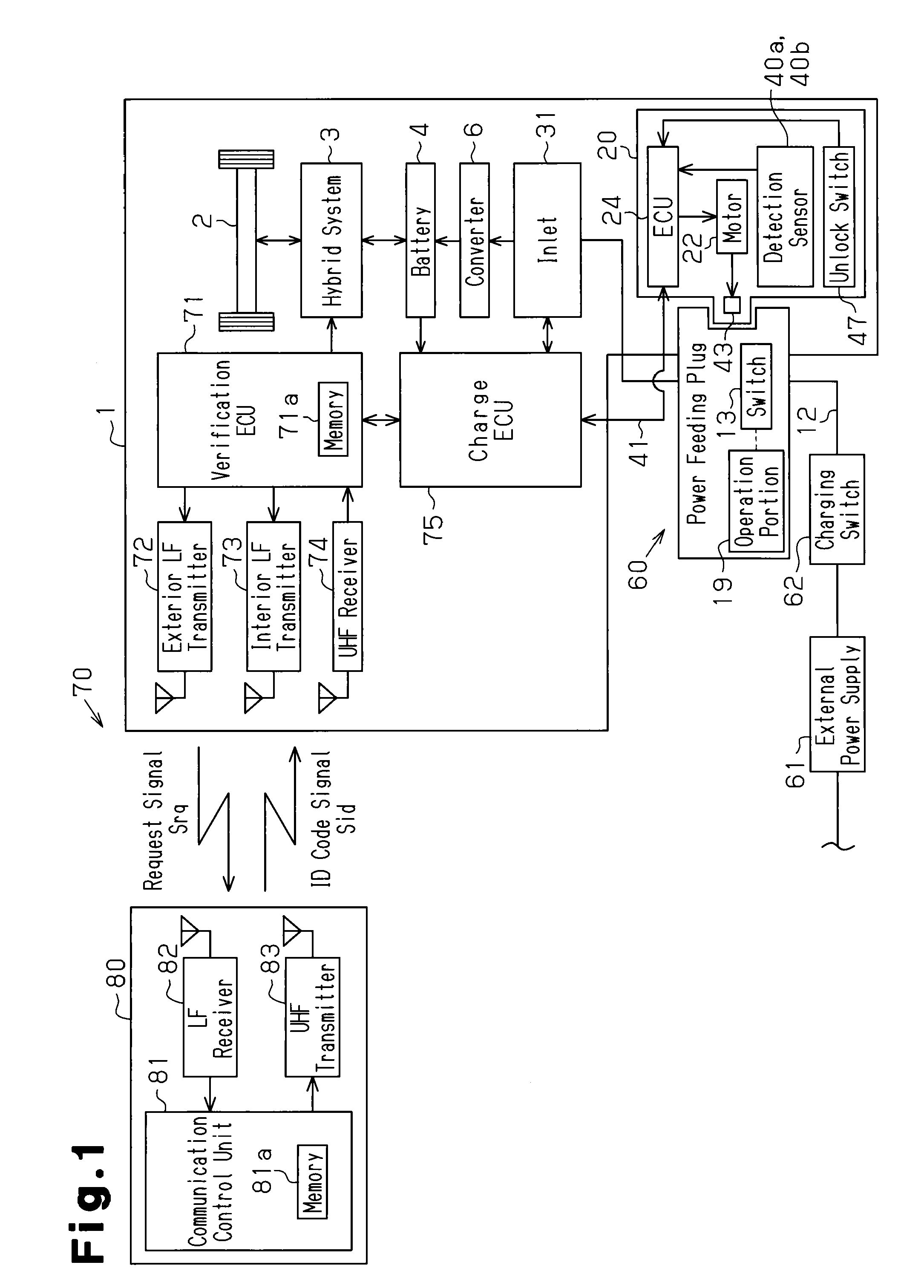
[0022]Referring to FIG. 1, a hybrid vehicle 1 includes a hybrid system 3, which uses a combination of an engine and a motor as a drive source to rotate drive wheels 2. The hybrid system 3 operates in a plurality of modes. More specifically, the hybrid system 3 operates in a mode using only the engine to drive the wheels 2, a mode using the motor while generating electric power with the engine to drive the wheels 2, a mode using both the engine and the motor to drive the wheels 2, and a mode using only the motor to drive the wheels 2.

[0023]The vehicle 1 includes a battery 4 that supplies power to the motor of the hybrid system 3. The battery 4 is chargeable by power generated by the engine and by an external power supply 61, which is connectable to the vehicle 1.

[0024]Further, the vehicle 1 includes an electronic key system 70 that, for example, locks and unlocks...


PUM


Abstract

A locking device that locks a power feeding plug to an inlet of an plug-in vehicle to restrict removal of the power feeding plug from the inlet. The locking device includes a housing coupled to the inlet. The housing covers a peripheral portion of the inlet and includes a hook port that receives the hook when the power feeding plug is inserted into the inlet. A lock bar, which is arranged in the housing, moves between a lock position, in which the lock bar locks the hook to the inlet, and an unlock position, in which the lock bar permits the hook to move relative to the inlet. The lock bar, when located at the lock position, blocks the hook, which is hooked to the inlet, to restrict removal of the housing from the inlet.

Description

CROSS-REFERENCE TO RELATED APPLICATIONS[0001]This application is based upon and claims the benefit of priority from prior Japanese patent application No. 2010-121782, filed on May 27, 2010, the entire contents of which are incorporated herein by reference.BACKGROUND OF THE INVENTION[0002]The present invention relates to a plug locking device.[0003]Electric vehicles, which reduce carbon dioxide emissions, have become popular in recent years. Such an electric vehicle uses a battery to power a motor. Whenever the state of charge of the vehicle battery becomes low, the battery is charged, for example, with a household outlet or at a charging station. Japanese Laid-Open patent Publication No. 9-161898 describes a power feeding plug connected to a distal end of a power cable. The power feeding plug is connected to an inlet of a vehicle to charge the vehicle battery.[0004]The time required to charge the battery of an electric vehicle is still much longer than the time required to refuel a ...

Claims


Application Information

Patent Timeline
Patent Type & Authority Patents(United States)
IPC IPC(8): H01R13/62
CPCB60L11/1818H01R13/6397B60L11/14B60L11/1846H01R13/6275Y02T10/70Y02T10/7005Y02T90/121Y02T90/14B60L2270/32B60L2270/34Y02T10/7077Y02T90/163Y02T90/169Y02T90/128Y04S30/14Y02T10/7072B60L53/16B60L50/16B60L53/65Y02T90/12Y02T90/167Y02T90/16
Inventor KATAGIRI, TOSHIHARUKAHARA, KEIJI
Owner KK TOKAI RIKA DENKI SEISAKUSHO
Why Eureka
Try Eureka