
Quasi-phase matched optical waveguide for preventing back conversion

a quasi-phase matching and optical waveguide technology, applied in the field of optical waveguides, can solve the problems of destroying the conversion wave interference of the coupling component, and reducing so as to prevent the back conversion process and increase the energy of the conversion wave. , the effect of preventing the back conversion

Inactive Publication Date: 2013-01-22
I-SHOU UNIVERSITY
View PDF2 Cites 0 Cited by
  • Summary
  • Abstract
  • Description
  • Claims
  • Application Information

AI Technical Summary

Benefits of technology

[0009]Another object of the present invention is to provide a method of preventing back conversion that occurs in a QPM waveguide during the generation of a conversion wave.
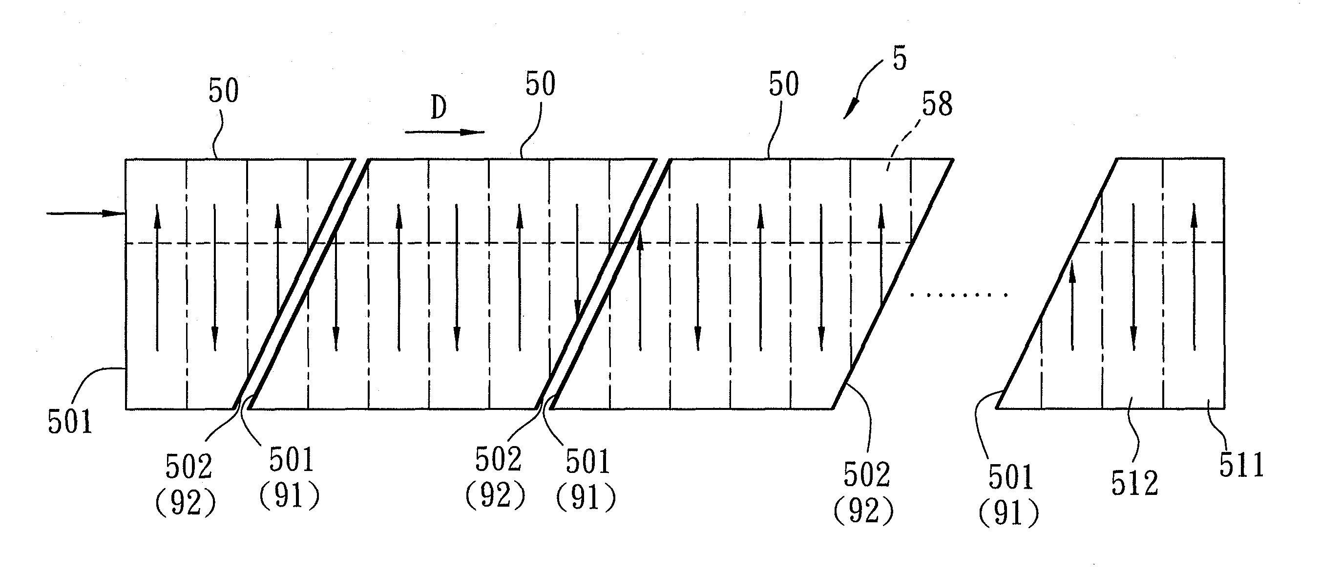
[0011]According to another aspect of the present invention, a method of preventing a back conversion process occurring during generation of a conversion wave by coupling a second harmonic wave of a pump wave with a signal wave, comprises: providing an optical substrate that is periodically poled and that has a waveguide part extending along a wave propagation direction; launching the pump and signal waves into the waveguide part to generate the second harmonic wave and the conversion wave; determining a propagation distance for at least one location where the conversion wave starts to decline due to back conversion; sectioning the optical substrate at the location so that the optical substrate is divided into at least two sections each of which has a wave input facet and a wave output facet; disposing a band-pass filter layer at the location and on the wave input facet of one of the sections to filter out the signal wave for preventing back conversion.
[0012]As the signal wave is removed, the back conversion process can be eliminated, and the second harmonic wave can continuously couple its energy to both of signal and conversion waves. Therefore, the energy of conversion wave can increase further.

Problems solved by technology

When the phase difference between the conversion wave and its coupling component is out of phase, the coupling component destructively interferes with the conversion wave and reduces the energy of the conversion wave.
The process by which pulse energy of the conversion wave declines is called back-conversion which, apparently, reduces the conversion efficiency of the conversion wave of the cascaded SHG+DFG process.
But such a chirp QPM waveguide is not suitable for high power situations.
However, as the second harmonic wave is important and cannot be removed, it is only the signal wave that can be removed to prevent back conversion.

Method used


Image

  • Quasi-phase matched optical waveguide for preventing back conversion
  • Quasi-phase matched optical waveguide for preventing back conversion
  • Quasi-phase matched optical waveguide for preventing back conversion

Examples


Embodiment Construction

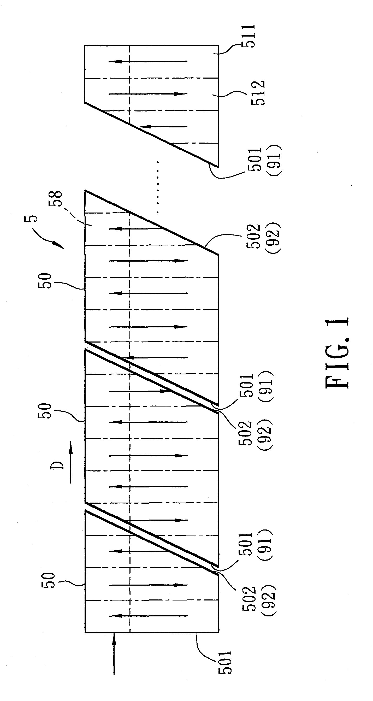
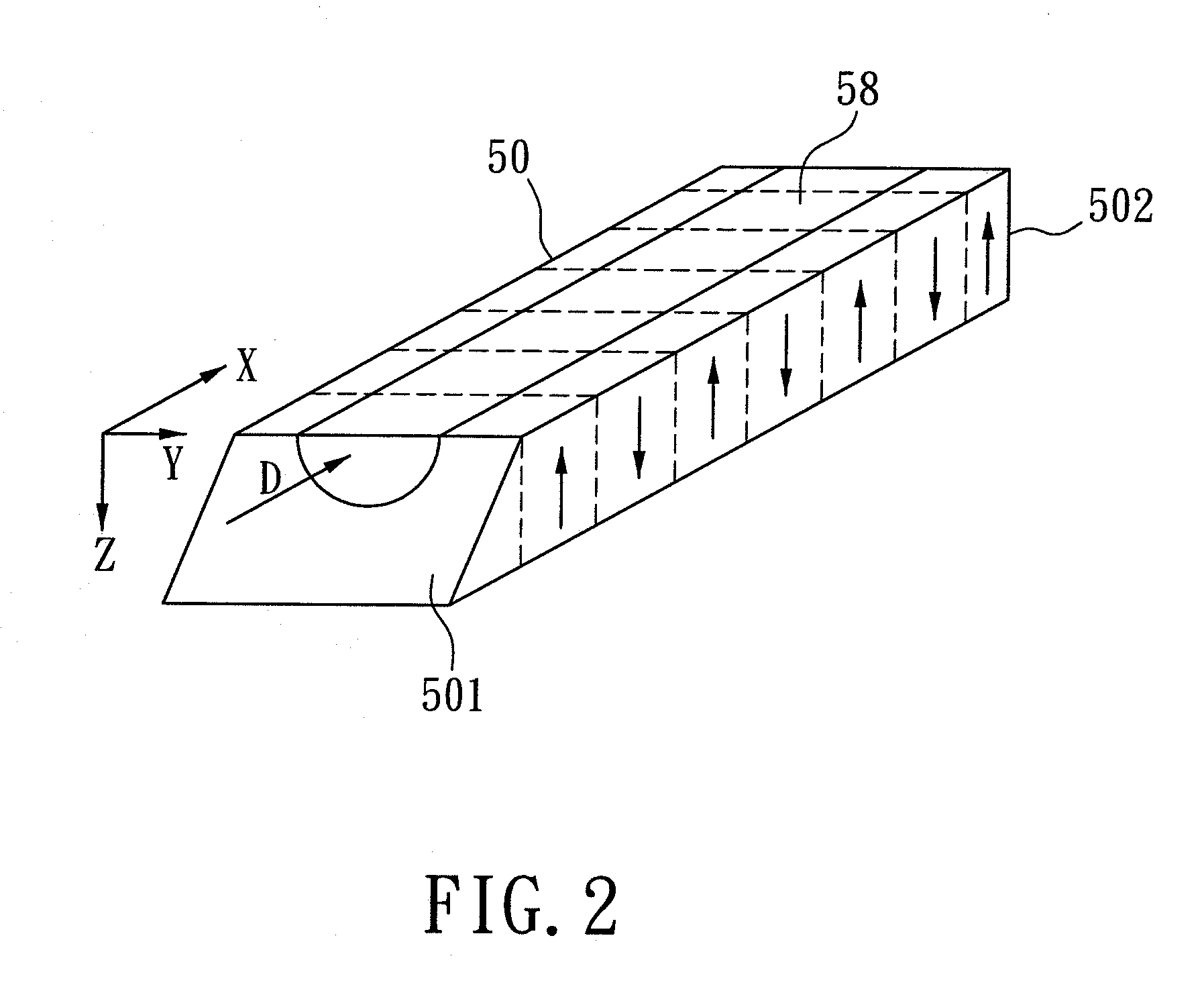
[0021]Referring to FIGS. 1 and 2, there is shown a QPM waveguide device which includes an optical substrate 5 that is divided into a plurality of sections 50. The optical substrate 5 is made from a ferroelectric material that can be polarized periodically and that exhibits a stable polarity at high temperature. Examples of the ferroelectric materials include LiNbO3, LiTaO3, GaAs, KTiOPO4, RbTiOPO4, RbTiAsPO4, KH2PO4, BaB2O4, CsB3O5 and KTiOAsO4. In this embodiment, the optical substrate 5 is made from LiNbO3.

[0022]Referring to FIGS. 3 and 4, there is shown a fabrication process for fabricating the optical substrate 5. In the process, an aluminum grating 52 is formed on an upper surface of a plate 10 made of LiNbO3, and includes a plurality of aluminum strips 521. The gaps between the aluminum strips 521 are filled by strips of a photoresist pattern 522. To conduct a thermal poling process, the aluminum grating 52 and the photoresist pattern 522 are covered by a layer of a liquid ele...


PUM

PropertyMeasurementUnit
temperatureaaaaaaaaaa
propagation distanceaaaaaaaaaa
energyaaaaaaaaaa

Abstract

A QPM waveguide includes an optical substrate having periodic domain-inverted regions and non-inverted regions which are arranged alternately, and a waveguide part passing through the domain-inverted regions and non-inverted regions. The substrate is divided into at least two sections each of which has a wave input facet and a wave output facet. At least one band-pass filter layer is disposed on the wave input facet of one section to filter out a signal wave for preventing back conversion so that the energy of the conversion wave can increase. A method for preventing the back conversion is also disclosed.

Description

BACKGROUND OF THE INVENTION[0001]1. Field of the Invention[0002]The invention relates to an optical waveguide, more particularly, to a quasi-phase matched optical waveguide for preventing a back conversion process occurring during the generation of a conversion wave.[0003]2. Description of the Related Art[0004]Quasi-phase matched (QPM) waveguide devices such as periodically poled lithium niobate waveguides have been applied in optical sampling systems and all-optical logic processes. Such optical sampling systems and all-optical logic processes are based on a specific cascaded quadratic nonlinear process χ2:χ2 in a QPM waveguide to induce cascaded second-harmonic generation (SHG) and difference-frequency generation (DFG). In the cascaded SHG+DFG process, a launched pump wave (P wave) generates its second harmonic wave (PP wave) via a SHG process, and then the second-harmonic wave immediately interacts with another launched signal wave (S wave) to generate a conversion wave (C wave) ...

Claims


Application Information

Patent Timeline
Patent Type & Authority Patents(United States)
IPC IPC(8): G02F1/35H01S3/10
CPCG02F1/3775
Inventor LIN, SHIH-CHIANGSUN, NAI-HSIANGCHIANG, PO-JUI
Owner I-SHOU UNIVERSITY
Learn More