Roughness insulated sheath covering

a technology of roughness insulation and sheath covering, which is applied in the direction of snap fasteners, general fasteners, buckles, etc., can solve the problems of significant physical disruption of the underlying fastener, more unwanted abrasion, and the wearer’s “roughness” factor, so as to reduce the amount of time wasted

Active Publication Date: 2013-01-29
LEADTHEWAY HOOK & EYE TAPE HONG KONG
View PDF8 Cites 12 Cited by
  • Summary
  • Abstract
  • Description
  • Claims
  • Application Information

AI Technical Summary

Benefits of technology

[0013]First, an insulative sleeve has ultrasonically cut slits for admitting the attachment eyelets. This technique is to form slits in the enveloping roughness insulative layer of material which are sized to admit the “U” protrusions of the female eyelet members through each respective one of the ultrasonically cut slits using generated heat. The first advantage of using ultrasonically cut slits is that a close controlled tolerancing of the width of the ultrasonically cut slits with respect to the “U” protrusions of the female eyelet to insure that there is no significantly exposed slit that might catch on another structure. The second advantage is that the use of ultrasonics with ultrasonically generated heat forms a melt stabilization of the material to insure that no unraveling will take place. Third, the angle of cut can be adjusted to facilitate guiding of the “U” protrusions of the female eyelet through the formed slits. Fourthly, the slits can be formed into an enveloping roughness insulative layer of material independently and separately from steps involving formation of the underlying support, and attachment of the female eyelet onto the underlying support. Where the enveloping roughness insulative layer of material has portions of its area located “away” from the formed slits, it enables the precision of placement of the slits to be matched generally with the placement of the female eyelets. Put another way, the enveloping roughness insulative layer of material can have extra material, or even thicker material, to thus relax the overall tolerance with respect to the support layer.
[0014]Fifthly, the elimination of the need to be primarily concerned with how the enveloping roughness insulative layer of material attaches to the main support enables a relaxation of the constraints by which the remainder of the enveloping roughness insulative layer of material is either attached to the main support, attached to the main garment, or attached to itself in closure. In this manner, the enveloping roughness insulative layer of material can be controlled with respect to the main support by means other than direct attachment to it. The enveloping roughness insulative layer of material can be fitted to stretch against the end of the support not attached to the main garment material. The enveloping roughness insulative layer of material can be stretched against the slits which admit the “U” protrusions of the female eyelet through the formed slits. In another example, where the open end of the enveloping roughness insulative layer of material which would lie adjacent to the main clothing connector end to which the main support would attach, the enveloping roughness insulative layer of material may be left lightly attached. Such light attachment may be just enough to insure that the enveloping roughness insulative layer of material slits do not slip off the “U” protrusions of the female eyelet. Almost finally, where there are any seams necessary to complete the enveloping roughness insulative layer of material, those seems need not occur evenly at the planar edge of the support material. The enveloping roughness insulative layer of material can be formed with a pair of planar expanses which are uneven to cause the joining seams to lie on one side of the planar support, and away from the portion of the enveloping roughness insulative layer of material which comes into contact with the user's skin. And finally, the enveloping roughness insulative layer of material can be formed as a tube so that it has no upper and lower edge joinder, leaving only an end edge and a portion which is adjacent the point of attachment to the main expanse of material.
[0016]Further, because the enveloping roughness insulative layer of material covers the eyelet side of the connector very closely toleranced to the area immediately adjacent the “U” protrusions of the female eyelet, the male hook members essentially have no obstructions on which to “falsely catch” when being engaged with the “U” protrusions of the female eyelet. This enables the male bearing clothing connector to slide until engaged by a female eyelet. This reduces time wasted in dealing with annoying false catches during the engagement and fastening process by the user.
[0017]The ability to use a roughness insulated sheath covering frees the designer to use a wider variety of materials for the support for the female eyelets. The female eyelets can be supported on a material which is stronger and needle resistant. The attachment of the female eyelets to the support material is similarly freed. Female eyelet attachment can be accomplished by forming the support around the female eyelets, by ultrasonic implacement into the female eyelet support material, or by folding of the support material and gluing or welding about the bases of the female eyelets.
[0019]Further, the combination of the eyelet support and roughness insulative layer of material can be formed as a turned out structure where it is desired to insert the “U” protrusions of the female eyelet members through each respective one of the ultrasonically cut slits before the roughness insulative layer of material is formed into an envelope. In this case the eyelet support can be turned inside out, along with the side of the roughness insulative layer of material stabilized. The eyelet support will ideally be stabilized adjacent the layer of the roughness insulative material having the cut slits so that the “U” protrusions of the female eyelet members extending through each respective one of the ultrasonically cut slits will not be pulled back through the slits. Stabilization can be accomplished by adjacent gluing, or by shaping the “U” protrusions of the female eyelet members to resist being pulled back through the slits either by frictional contact, or providing a “U” shaped protrusion of the female eyelet members to engage the slot frictionally or as a forcefully pulled through locking engagement.

Problems solved by technology

The support of the fastener is the more critical factor, with the attachment of the fastener to an underlying structure requiring a significant invasion of the underlying fastener, such as by stitching, forming a significant physical disruption to the underlying fastener.
These lateral disruptions produce a “roughness” factor to the wearer, particularly where the structures have significant force bearing capability.
The problems of this approach include the addition of the soft layer to an already thickened set of layers necessary to support the force of the connector and transmit it effectively to the underlying attachment material.
Bulkiness of the support material which supports the connectors or fasteners adds to the roughness by providing an expanded member which is naturally pressed even more tightly against to the body to thus cause even more unwanted abrasion.
In addition, most sewn flaps are subject to the same sewing rigors as the layers of material they are trying to protect.
The standard use of a multi-layered support structure can require a significant amount of sewing, bolting, stapling and not including the portion of the structure which attaches to another structure.
The ability to reduce the main attachable support structure while at the same time providing a soft insulative material has presented an insurmountable problem.
Part of the obstacle in this problem is the cost of manufacture.
The connecting portions of a garment are of higher cost than the main expanses of material, require more labor to construct, and are the focal point of quality control as a failure is more likely occur at an attachment point.
The multiple labor steps and multiple structure steps add multiply the potential for quality failure.
Thus, both a covering flap attached to the main support and the attachment of the eyelets to the main support can make the roughness problem worse.
In most cases, a softness layer may be precluded from attachment to a non-sewable eyelet support, either because the method of attachment of the softening layer creates a rougher projection (such as gluing or stapling), or where stitching might not be able to penetrate the main support.
Where a manufacturer must justify each minute fractional addition to the garment, a decision may have to be made to use a connector which is not roughness insulated if its cost is too high, or even if it is not sufficiently competitively low.

Method used


Image

  • Roughness insulated sheath covering
  • Roughness insulated sheath covering
  • Roughness insulated sheath covering

Examples


Embodiment Construction

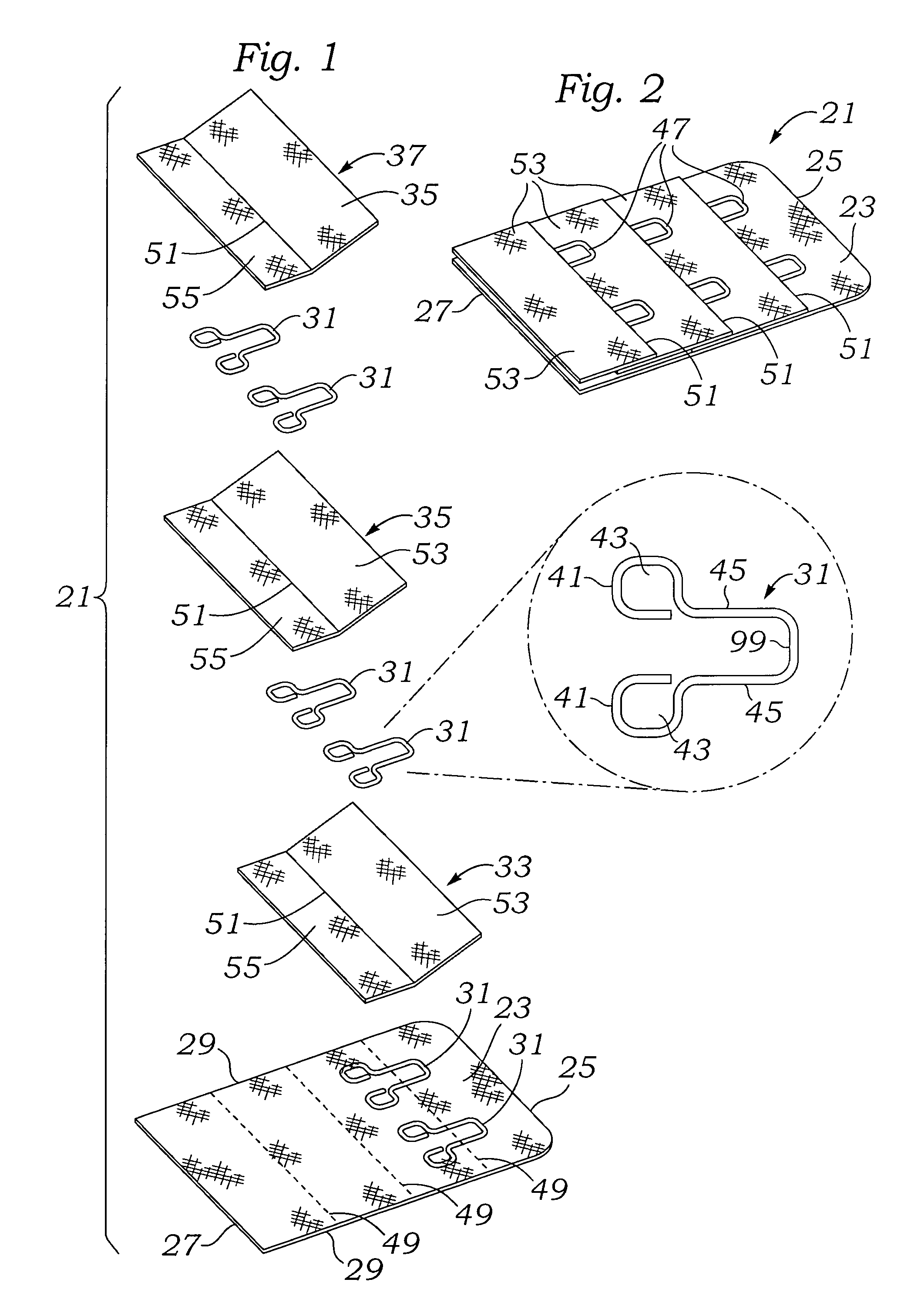
[0032]Referring to FIG. 1, an exploded perspective view of one possible configuration of an eye loop support structure 21 is shown as having a base layer 23 which can be made of any material depending upon the manner of attachment. Base layer 23 has a trailing end 25 and an attachment end 27, and a pair of side edges 29. The eye loop support structure 21 illustrated for example is formed with a base layer onto which is located a series of female eye loop connectors 31 and folded and sewn layers 33, 35, &37 are attached.

[0033]An expanded view of one possible female eye loop connector 31 is seen to the right side of FIG. 1. The eye loop connector 31 is typically made from a small wire that has been cut and bent to a shape similar to that shown, or it could be any shape. Because the example shown is a sewn example, the shape of FIG. 1 works well with a sewn attachment. The eye loop connector 31 includes a pair of base eyelets 41 which may be formed with each having an opening 43 which ...


PUM


Abstract

An enveloping roughness insulative layer of material is provided which need have no connection to a connection member, such as a female eyelet support before the female eyelet support and enveloping roughness insulative layer of material is attached to the main garment structure. The enveloping roughness insulative layer of material can be formed while attached to a connection member or it can be formed independent of the connection member. The enveloping roughness insulative layer of material is preferably formed into an envelope shape and may be made from a planar layer of material or result in closure of an annular tubular expanse of material.

Description

BACKGROUND OF THE INVENTION[0001]This invention relates to an improved method and technique for attachment of a roughness insulating sheath covering to enable roughness insulation of any of a variety of structures to which the sheath may be attached, with structural engagement through members extending through the sheath.BACKGROUND OF THE INVENTION[0002]A number of varieties of clothing have connector structures which must provide substantial holding ability. In general, where a fastener is used, the underlying structure is such that it must support a fastener and also the lateral forces necessary for clothing support. The support of the fastener is the more critical factor, with the attachment of the fastener to an underlying structure requiring a significant invasion of the underlying fastener, such as by stitching, forming a significant physical disruption to the underlying fastener. These lateral disruptions produce a “roughness” factor to the wearer, particularly where the stru...

Claims


Application Information

Patent Timeline
Patent Type & Authority Patents(United States)
IPC IPC(8): A44B13/00
CPCA41F1/006A44D2211/00Y10T24/45958Y10T24/27Y10T24/45225
Inventor YEUNG, KAM YUEN RICKY
Owner LEADTHEWAY HOOK & EYE TAPE HONG KONG
Why Eureka
Try Eureka