Corrector

Active Publication Date: 2013-01-29
CEOS CORRECTED ELECTRON OPTICAL SYST
View PDF6 Cites 0 Cited by
  • Summary
  • Abstract
  • Description
  • Claims
  • Application Information

AI Technical Summary

Benefits of technology

The present invention relates to a corrector for an electron microscope that reduces the impact of fluctuations in power supply on image quality and resolution. The inventive corrector achieves this by reducing sensitivity to changes in field strengths caused by fluctuations in power supply. To achieve this, the corrector is designed in a way that reduces the impact of axial fundamental rays in the first quadrupole, which are involved in generating the stigmatic intermediate image of the axial fundamental rays. This reduces the effort required for a highly stable power supply and avoids impairment of image quality. Additionally, the invention proposes a readjustment of the duodecapole fields of the third and fourth multipole elements to eliminate higher-order aberrations that may occur due to changes in the beam path caused by the insertion of transfer lenses and modifications to the system settings.

Problems solved by technology

However, for correction to be successful, such maxima are only required in the third or fourth quadrupole.

Method used


Image

  • Corrector
  • Corrector
  • Corrector

Examples


Embodiment Construction

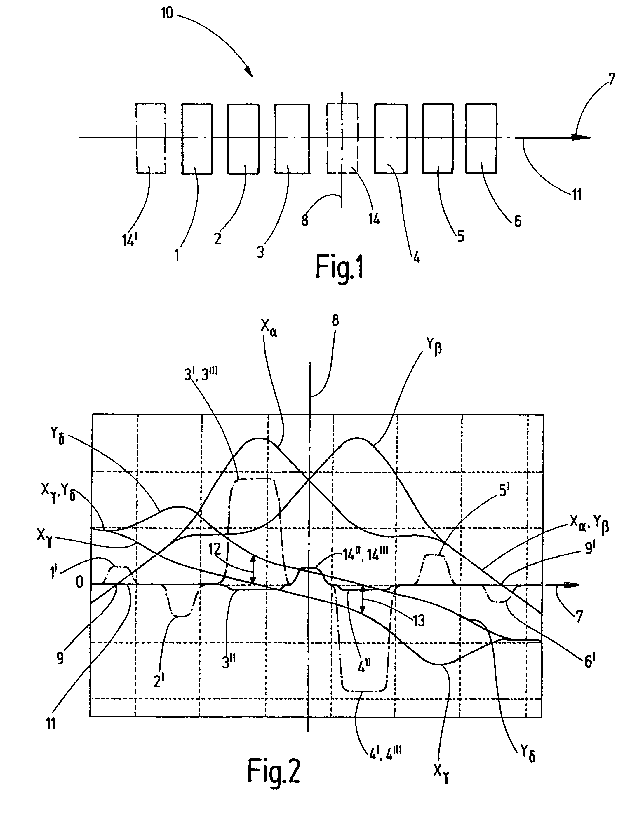
[0039]FIG. 1 shows a schematic view of the inventive corrector 10. A first multipole element 1, a second multipole element 2 and a third multipole element 3 are disposed along the optical axis 11 in the direction of the beam path 7. After a plane of symmetry 8, three multipole elements 4, 5, 6 then follow, wherein these are symmetric to the multipole elements 1, 2 and 3 with respect to their configuration and must also be installed symmetrically with respect to the plane of symmetry 8. The multipole element 1 corresponds to the multipole element 6; the multipole element 2, to the multipole element 5; and the multipole element 4, to the multipole element 3.

[0040]As a further embodiment of the basic idea of the invention, a further multipole element 14 (shown dashed) can be disposed in the plane of symmetry 8. Alternatively, the further multipole element 14′ (shown dotted-and-dashed) can also be disposed outside the six multipole elements 1, 2, 3, 4, 5 and 6.

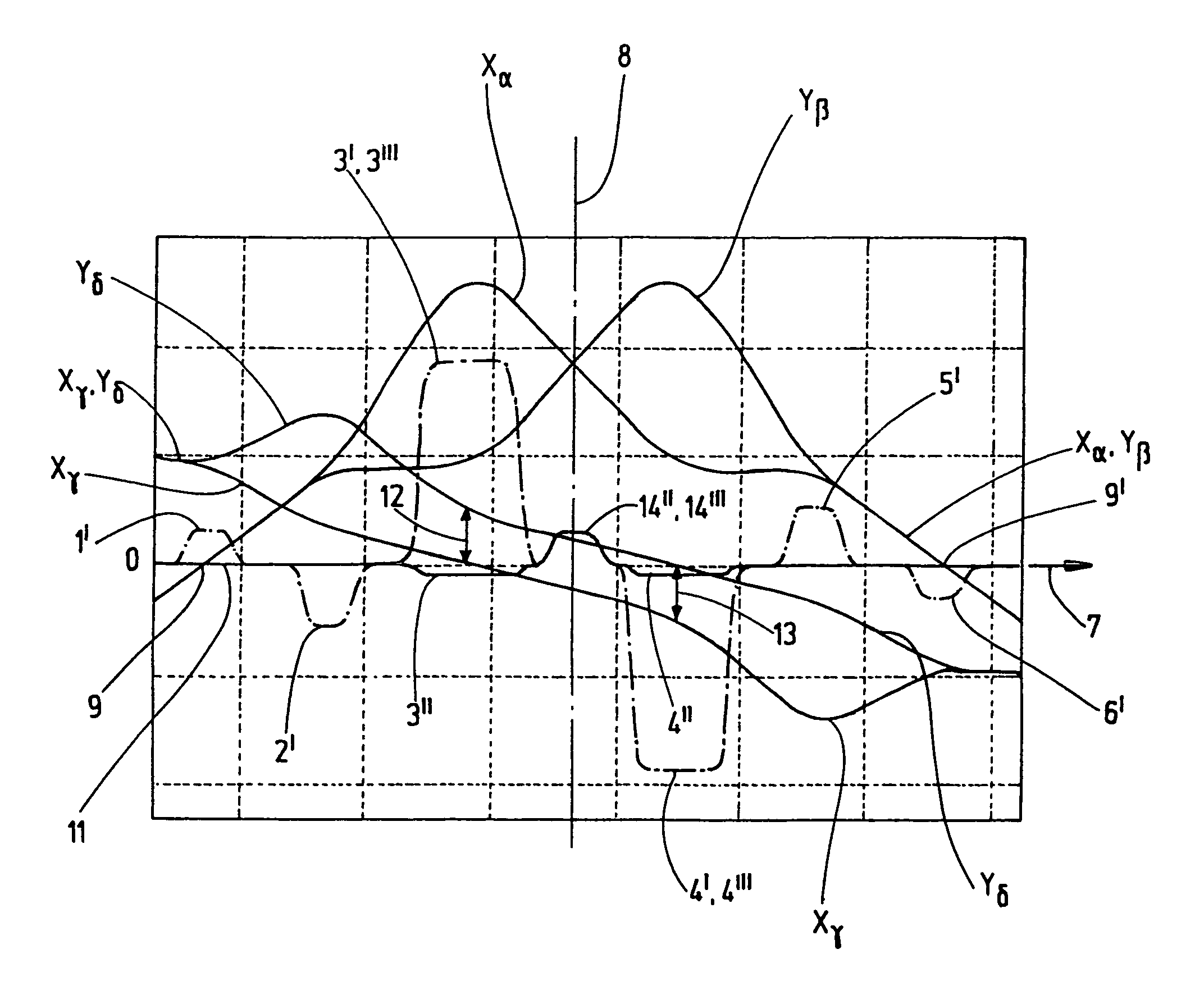
[0041]FIG. 2 shows the bea...


PUM


Abstract

A corrector (10) for an electron microscope is proposed which is less sensitive to fluctuations of the electrical power supply if a stigmatic intermediate image (9) of the axial fundamental rays (xα, yβ) is produced in the quadrupole field (1′) of a first quadrupole element (1) and this quadrupole field (1′) is set such that astigmatic intermediate images (12, 13) of the off-axial fundamental rays (xγ, yδ) are produced in the region of the center of the quadrupole fields (3′, 4′) of a third (3) and fourth multipole element (4) and there also, due to the setting of the quadrupole field (2′) of a second quadrupole element (2), the axial fundamental rays (xα, yβ) of the same section (x, y) as that, in which the intermediate images (12, 13) of the off-axial fundamental rays (xγ, yδ) are located, each exhibit a maximum.

Description

BACKGROUND OF THE INVENTION[0001]The invention relates to a corrector for correcting chromatic and spherical aberrations in an electron microscope with six multipole elements disposed consecutively in the beam path such that they are symmetric about a plane of symmetry, of which all are used for generation of quadrupole fields and the third and fourth also for generation of octupole fields, wherein the latter are oriented in the same direction and the quadrupole fields of all six multipole elements are rotated through 90° from one to the next and are centrosymmetric about the point of intersection between the optical axis and the plane of symmetry, wherein the following exchange symmetries are produced: exchange symmetry of the axial fundamental rays with the plane of symmetry as the reflection plane for exchange of the trajectory of the axial fundamental rays, and exchange symmetry of the off-axial fundamental rays with the point of intersection between the optical axis and the pla...

Claims


Application Information

Patent Timeline
IPC IPC(8): H01J37/141
CPCH01J37/153H01J2237/2802H01J2237/28H01J2237/1534
Inventor ZACH, JOACHIMUHLEMANN, STEPHAN
Owner CEOS CORRECTED ELECTRON OPTICAL SYST
Why Eureka
Try Eureka