Conveyor pan with changeable trough, and a changeable trough

a technology of conveyor pan and changeable trough, which is applied in the direction of cutting machine, earthwork drilling and mining, transportation and packaging, etc., can solve the problems of generally being subject to substantially greater wear on the top strand than on the bottom strand, and achieve the effect of relieving the load on the screw bolt joints

Active Publication Date: 2013-02-05
CATERPILLAR INC
View PDF10 Cites 6 Cited by
  • Summary
  • Abstract
  • Description
  • Claims
  • Application Information

AI Technical Summary

Benefits of technology

[0004]An object of the invention is to provide a conveyor pan provided with an easily changeable trough which can be fixed securely in place.
[0005]This object and others are achieved in terms of the conveyor pan and in terms of the changeable trough by the fact that at least the top web of one of the two side profiles is provided with a plurality of open-edged indentations, in which there are welded holding strips which project laterally partially over the top web and are provided with a plurality of bolt holes for the passage of a plurality of screw bolts. In the conveyor pan according to the invention or a changeable trough according to the invention, the fixing in place is hence realized via a plurality of screw bolts, which pass through bolt holes in holding strips which are welded to the top webs of the side profiles such that they protrude laterally over the top webs. This not only ensures that the screw bolts are easily accessible and can be undone, for example, also by means of electric tools such as electric screwdrivers, but the provision of a plurality of screw bolts also serves to prevent possible vibrations or positional displacements of the changeable trough, as well as thereby induced noise loads, if a single screw bolt comes loose. The provision of a plurality of screw bolts hence simultaneously ensures a redundancy of the top strand fastening means.
[0008]In order to relieve the load upon the screw bolt joints, it is particularly advantageous if a shaped plate is welded on beneath the bottom plate of the changeable trough, and in the intermediate floor of the substructure a shaped cavity is formed, into which the shaped plate can at least partially be inserted in a positive-locking manner. Through the interaction of the shaped plate and the shaped cavity, all the forces which arise in the running direction of the scraper chain and which are generated, for example, by the transport of the material and / or the movement of the chain scrapers and scraper chain, can then be passed into the substructure, without the screw joints, or the loose holding strips engaging in the pocket, having to absorb these forces and pass them into the substructure.

Problems solved by technology

Since the won material is almost always transported in the top strand, since debris formations can also be permitted there, the top strand is generally prone to substantially greater wear than the bottom strand.

Method used


Image

  • Conveyor pan with changeable trough, and a changeable trough
  • Conveyor pan with changeable trough, and a changeable trough
  • Conveyor pan with changeable trough, and a changeable trough

Examples


Embodiment Construction

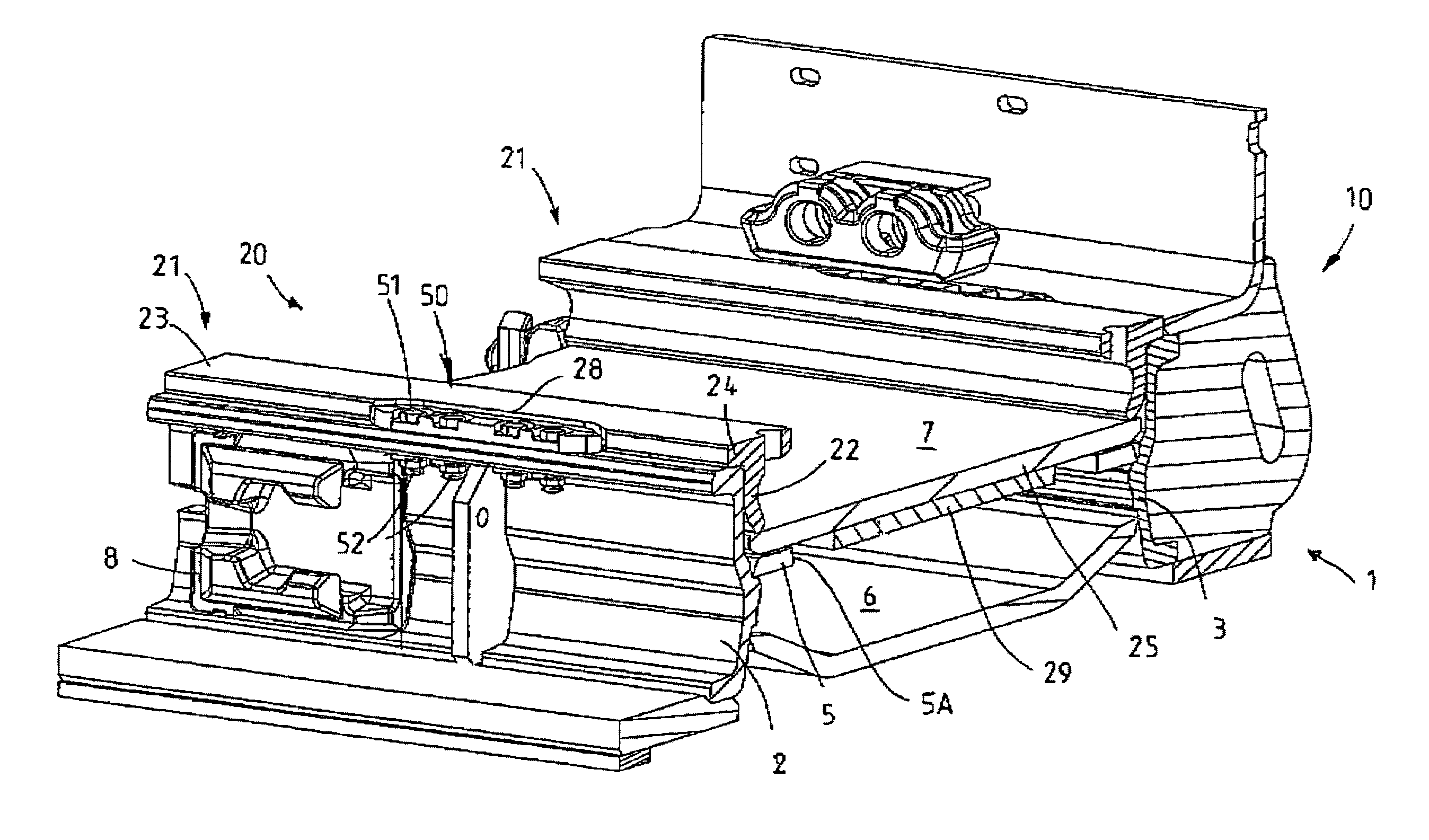
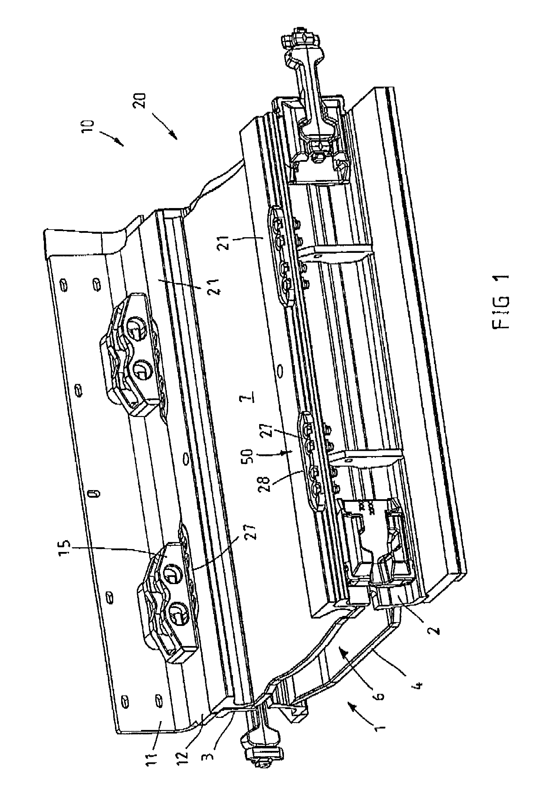
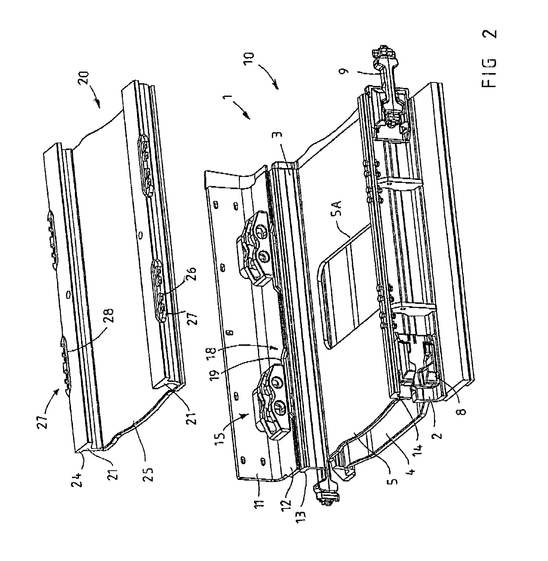
[0015]Referring now to the drawings wherein the showings are for the purpose of illustrating preferred and alternative embodiments of the invention only and not for the purpose of limiting same, the figures show a conveyor pan configured as a face conveyor for a drum cutter-loader used as a mining apparatus is indicated in its entirety by the reference symbol 10. With a plurality of identically configured conveyor pans 10, a further face conveyor (not represented) can be formed in order, with a scraper chain (likewise not represented) and the scrapers connected to this scraper chain, to convey minerals won with the drum cutter-loader from the face to a transfer station, at which the minerals are ejected onto a gate conveyor or a belt conveyor, as is known to the person skilled in the art of underground mining and in mineral extraction.

[0016]The conveyor pan 10 firstly consists of a substructure 1, which is here realized as a welded construction and comprises, as basic elements, a (i...


PUM


Abstract

A conveyor pan for a mining conveyor having a substructure with two side elements and an intermediate floor as well as a changeable trough forming a top strand and being detachably and exchangeably fastenable to the substructure. The trough having side profiles, each with a top web, and the top strand fastening means including screw bolts being fixable in place on the substructure. In order to ease an exchange of the trough, at least the top web of one side profile is provided with a plurality of open-edged indentations, in which there are welded holding strips, which project laterally over the top web and are provided with a plurality of bolt holes for the passage of a plurality of screw bolts.

Description

[0001]The invention relates to a conveyor pan for a mining apparatus, in particular an underground scraper chain conveyor in the form of a face conveyor or gate conveyor, comprising a substructure having two side elements, which are joined together by means of an intermediate floor and / or a bottom strand floor and define a bottom strand, and further comprising a changeable trough, which forms a top strand and is detachably and exchangeably fastened or fastenable to the substructure by means of top strand fastening means and which consists of a conveyor bottom and two substantially T-shaped side profiles, each with a top web, the top strand fastening means comprising screw bolts which can be fixed in place on the substructure. The invention also relates to a changeable trough for a conveyor pan of this type, comprising a conveyor bottom and comprising substantially T-shaped side profiles, each with a top web.BACKGROUND OF THE INVENTION[0002]In underground mining, the minerals which a...

Claims


Application Information

Patent Timeline
Patent Type & Authority Patents(United States)
IPC IPC(8): B65G19/28
CPCE21C35/12B65G19/287
Inventor SCHMIDT, SIEGFRIEDWIRTZ, JORG
Owner CATERPILLAR INC
Why Eureka
Try Eureka