Ultrasonic observing apparatus, control method for ultrasonic observing apparatus, ultrasonic observing system and ultrasonic diagnostic apparatus

Active Publication Date: 2013-02-05
OLYMPUS CORP
View PDF13 Cites 52 Cited by
  • Summary
  • Abstract
  • Description
  • Claims
  • Application Information

AI Technical Summary

Problems solved by technology

In addition, since the mechanical scanning ultrasonic endoscope or mechanical scanning ultrasonic probe cannot perform transmission for a plurality of times with an ultrasonic transducer being fixed at the same position, a scan is possible only in a B mode but not in a color flow mode.

Method used


Image

  • Ultrasonic observing apparatus, control method for ultrasonic observing apparatus, ultrasonic observing system and ultrasonic diagnostic apparatus
  • Ultrasonic observing apparatus, control method for ultrasonic observing apparatus, ultrasonic observing system and ultrasonic diagnostic apparatus
  • Ultrasonic observing apparatus, control method for ultrasonic observing apparatus, ultrasonic observing system and ultrasonic diagnostic apparatus

Examples


first embodiment

(First Embodiment)

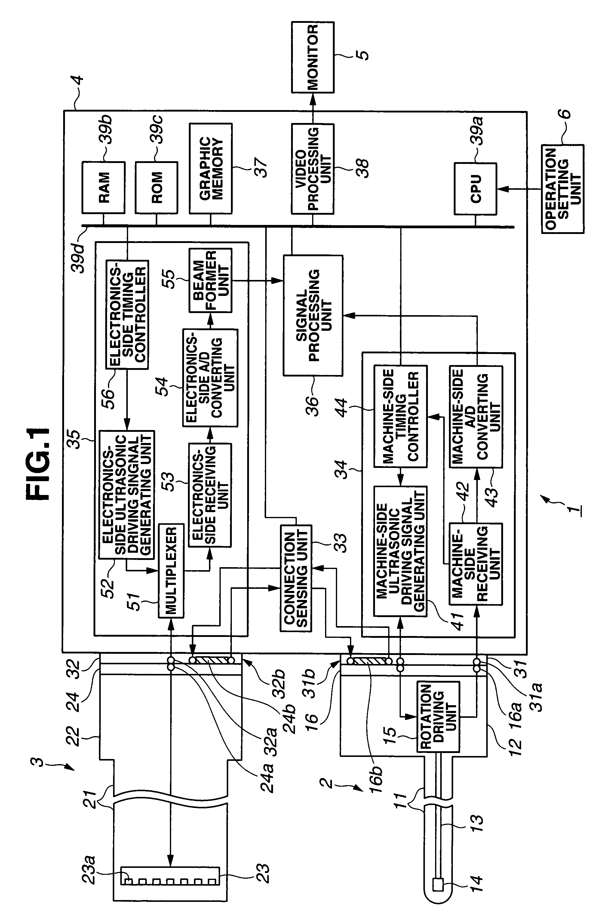
[0030]As shown in FIG. 1, an ultrasonic diagnostic apparatus 1 according to a first embodiment is configured of a mechanical scanning ultrasonic probe 2, an electronic scanning ultrasonic endoscope 3 and an ultrasonic observing apparatus 4. The ultrasonic observing apparatus 4 connects to a monitor 5 and an operation setting unit 6. The present embodiment uses the ultrasonic endoscope for the electronic scanning and the ultrasonic probe for the mechanical scanning.

[0031]The electronic scanning uses ultrasonic pulses of about 5 MHz for comparatively deep invasion and image pickup of an observed depth of a subject, enabling detailed diagnosis.

[0032]However, if the electronic scanning uses ultrasonic pulses of about 5 MHz, resolution is often insufficient. Therefore, higher frequencies are desired.

[0033]In the electronic scanning, a high-resolution ultrasonic probe of 20 to 30 MHz has not been realized because of many technical problems.

[0034]On the other hand, in the...


PUM


Abstract

An ultrasonic observing apparatus according to the present invention comprises a machine-side connector receptacle, an electronics-side connector receptacle, a mechanical echo signal detecting unit for detecting an echo signal obtained by receiving waves in a mechanical scanning ultrasonic probe connecting to the machine-side connector receptacle, an electronic echo signal detecting unit for detecting an echo signal obtained by receiving waves in an electronic scanning ultrasonic endoscope connecting to the electronics-side connector receptacle, and a signal processing unit for performing signal processing on the echo signal from the mechanical echo signal detecting unit and the echo signal from the electronic echo signal detecting unit.

Description

[0001]This application claims benefit of Japanese Application No. 2006-165215 filed in Japan on Jun. 14, 2006, the contents of which are incorporated by this reference.BACKGROUND OF THE INVENTION[0002]1. Field of the Invention[0003]The present invention relates to an ultrasonic observing apparatus, a control method for the ultrasonic observing apparatus, an ultrasonic observing system and an ultrasonic diagnostic apparatus for performing signal processing on an echo signal obtained by transmitting ultrasonic pulses from an ultrasonic transducer to living body tissue and receiving ultrasonic pulses reflected from the living body tissue to create an ultrasonic tomographic image.[0004]2. Description of the Related Art[0005]An ultrasonic diagnostic apparatus, conventionally, repetitively transmits ultrasonic pulses to living body tissue from an ultrasonic transducer and receives an ultrasonic pulse echo signal reflected from the living body tissue to display information in the living bo...

Claims


Application Information

Patent Timeline
Patent Type & Authority Patents(United States)
IPC IPC(8): A61B8/00
CPCA61B8/00A61B8/06A61B8/12A61B8/13A61B8/4411A61B8/4461A61B8/4488
Inventor MISONO, KAZUHIRO
Owner OLYMPUS CORP
Why Eureka
Try Eureka