Large-scale fabrication of vertically aligned ZnO nanowire arrays

a nanowire array, vertical alignment technology, applied in the field of nanostructures, can solve the problems of not being able to assemble the as-synthesized nanowire array into desired configurations at large scale, and none of the above approaches provides a reliable, high-throughput, and low-cost solution for large-scale fabrication

Inactive Publication Date: 2013-02-05
GEORGIA TECH RES CORP
View PDF34 Cites 17 Cited by
  • Summary
  • Abstract
  • Description
  • Claims
  • Application Information

AI Technical Summary

Problems solved by technology

Although the GAP technique can be used to fabricate a finite number of devices, it is rather challenging to assemble the as-synthesized nanowires into desired configurations at large scale.
However, none of the above approaches provides a reliable, high-throughput, and low-cost solution for large scale fabrication of patterned ZnO nanowire arrays at a level required for industrial applications.

Method used


Image

  • Large-scale fabrication of vertically aligned ZnO nanowire arrays
  • Large-scale fabrication of vertically aligned ZnO nanowire arrays
  • Large-scale fabrication of vertically aligned ZnO nanowire arrays

Examples


Embodiment Construction

[0016]A preferred embodiment of the invention is now described in detail. Referring to the drawings, like numbers indicate like parts throughout the views. Unless otherwise specifically indicated in the disclosure that follows, the drawings are not necessarily drawn to scale. As used in the description herein and throughout the claims, the following terms take the meanings explicitly associated herein, unless the context clearly dictates otherwise: the meaning of “a,”“an,” and “the” includes plural reference, the meaning of “in” includes “in” and “on.”

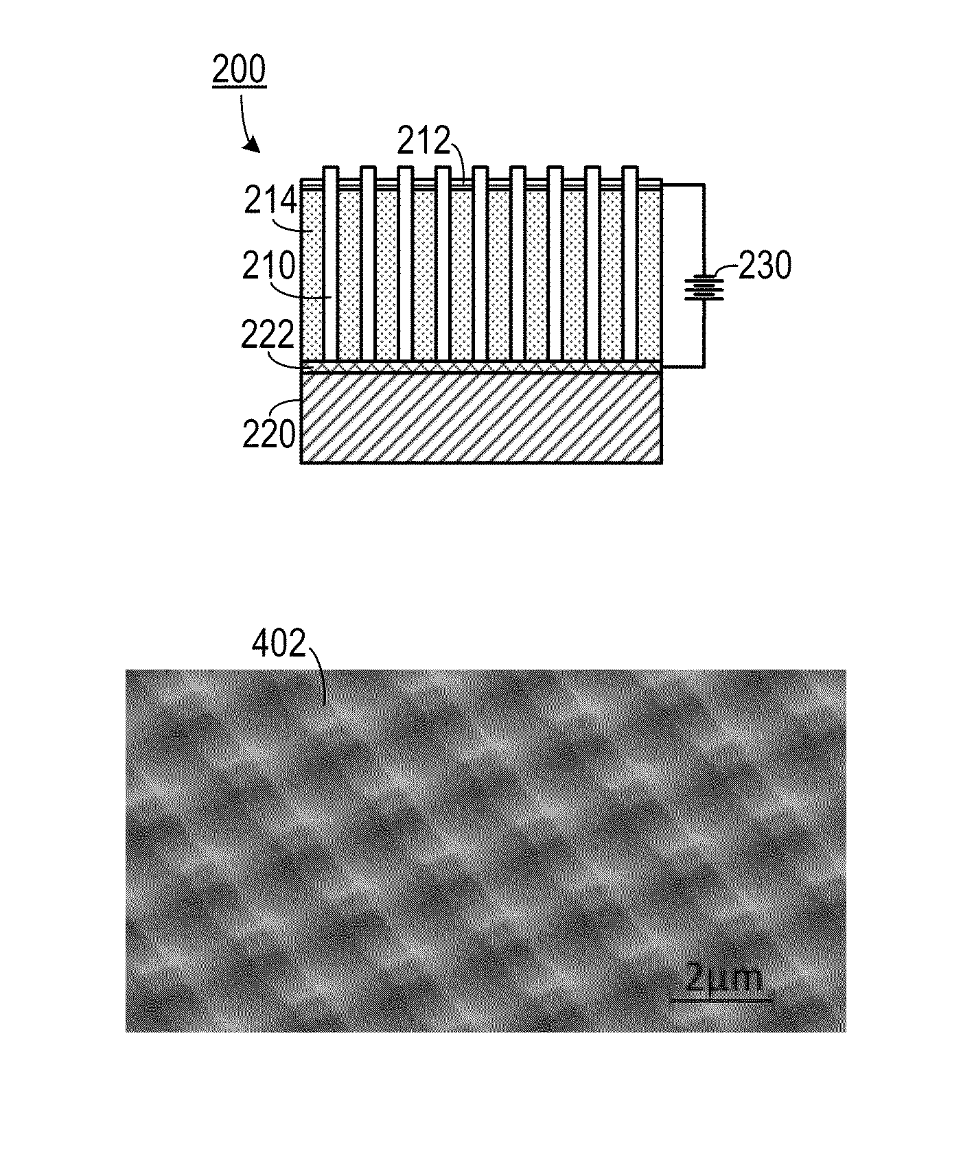
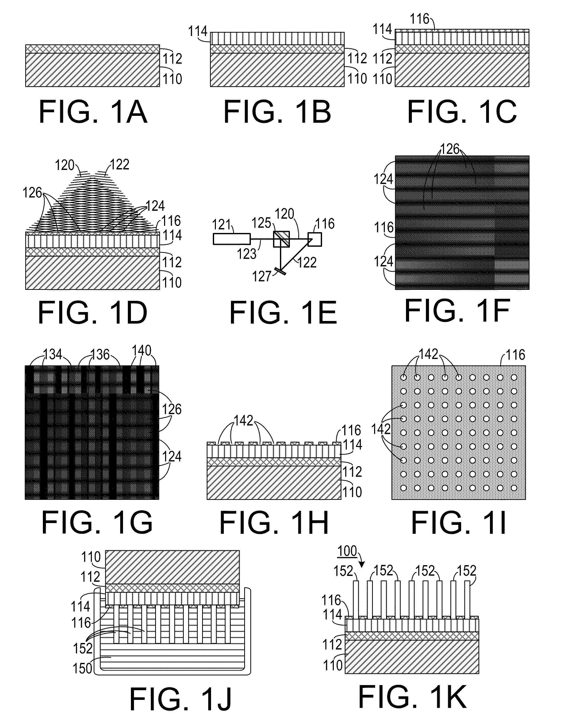
[0017]As shown in FIGS. 1A-1C, (which are cross-sectional views) one embodiment of a method of making nanowire arrays involves applying a ZnO seed layer 112 to a substrate 110, and then growing a layer 114 of dense nanowires 114 from the seed layer 112. A photoresist layer 116 is applied to layer 114 and the photoresist layer 116 is exposed to an interference pattern resulting from the interference of a first laser beam 120 and a secon...


PUM


Abstract

In a method for growing a nanowire array, a photoresist layer is placed onto a nanowire growth layer configured for growing nanowires therefrom. The photoresist layer is exposed to a coherent light interference pattern that includes periodically alternately spaced dark bands and light bands along a first orientation. The photoresist layer exposed to the coherent light interference pattern along a second orientation, transverse to the first orientation. The photoresist layer developed so as to remove photoresist from areas corresponding to areas of intersection of the dark bands of the interference pattern along the first orientation and the dark bands of the interference pattern along the second orientation, thereby leaving an ordered array of holes passing through the photoresist layer. The photoresist layer and the nanowire growth layer are placed into a nanowire growth environment, thereby growing nanowires from the nanowire growth layer through the array of holes.

Description

CROSS-REFERENCE TO RELATED APPLICATIONS[0001]This application claims the benefit of U.S. Provisional patent application Ser. No. 61 / 385,338, filed Sep. 22, 2010, the entirety of which is hereby incorporated herein by reference. This application also claims the benefit of U.S. Provisional patent application Ser. No. 61 / 326,422, filed Apr. 21, 2010, the entirety of which is hereby incorporated herein by reference. This application also claims the benefit of U.S. Provisional patent application Ser. No. 61 / 328,222, filed Apr. 27, 2010, the entirety of which is hereby incorporated herein by reference.STATEMENT OF GOVERNMENT INTEREST[0002]This invention was made with government support under contract No. DE-FG02-07ER46394, awarded by the Department of Energy and under contract No. W31P4Q-08-1-0009, awarded by the Department of the Army. The government has certain rights in the invention.BACKGROUND OF THE INVENTION[0003]1. Field of the Invention[0004]The present invention relates to nanost...

Claims


Application Information

Patent Timeline
Patent Type & Authority Patents(United States)
IPC IPC(8): H01L33/26B82Y40/00H01L21/36H01L33/04
CPCH01L21/02472H01L21/02494H01L21/02554H01L21/02603H01L21/02639H01L33/0087H01L33/08H01L33/18B82Y10/00B82Y40/00H01L33/28
Inventor WANG, ZHONG L.DAS, SUMANXU, SHENGYUAN, DAJUNGUO, RUIWEI, YAGUANGWU, WENZHUO
Owner GEORGIA TECH RES CORP
Why Eureka
Try Eureka