
Antenna circuit matching the soil conditions

a wireless subsurface sensor and antenna circuit technology, applied in the direction of electric signalling details, instruments, wireless commuication services, etc., can solve the problems of not being able the difficulty of closing the underground to above ground rf communication link, and the inability of certain wireless sensing devices to adapt to the soil conditions in real time, so as to optimize the utilization of resources, optimize turf health and playability, the effect of improving product quality

Active Publication Date: 2013-02-05
GREEN BADGE
View PDF23 Cites 4 Cited by
  • Summary
  • Abstract
  • Description
  • Claims
  • Application Information

AI Technical Summary

Benefits of technology

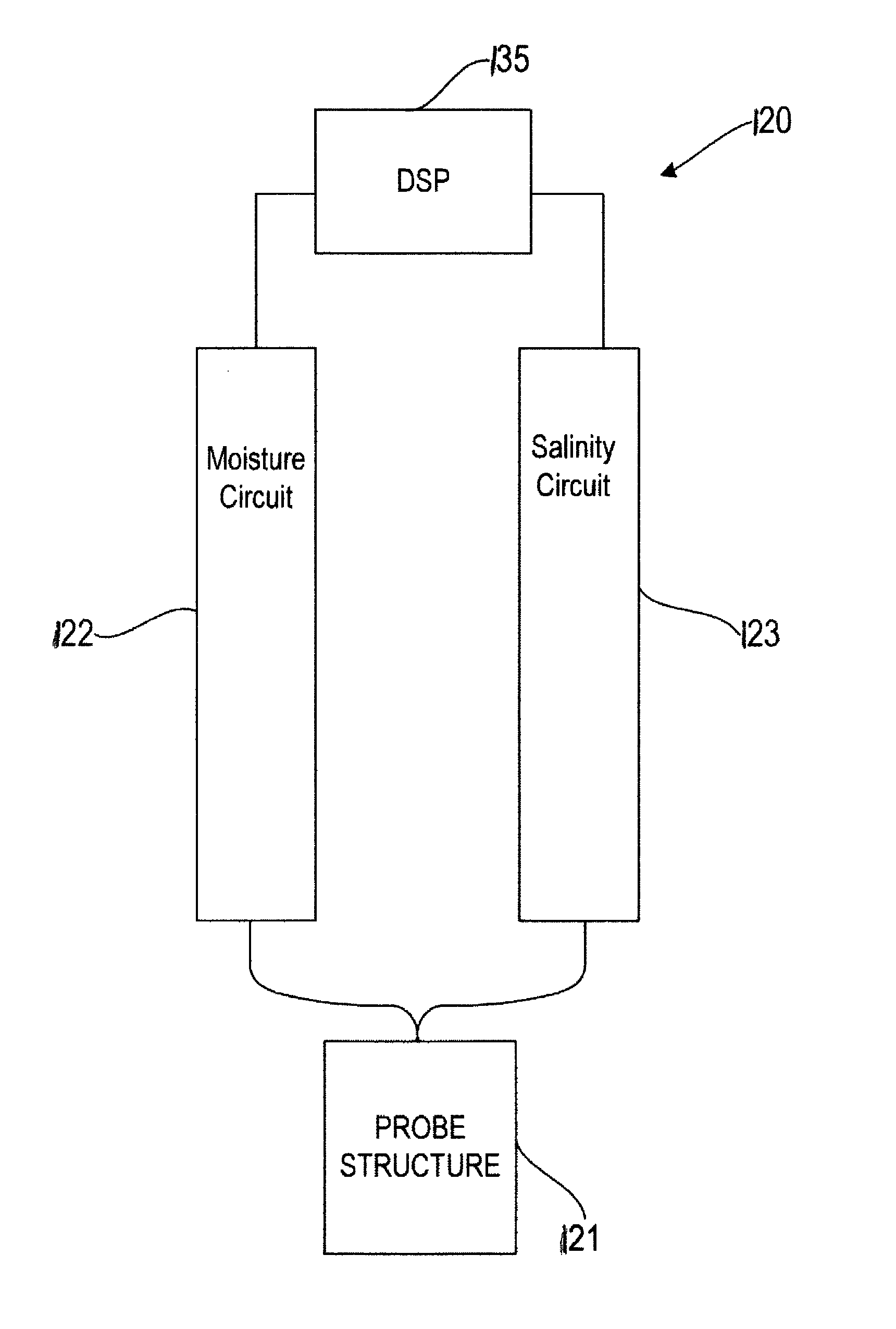
The present invention is a solution to the problem of soil moisture and salinity affecting wireless sub-surface soil sensors. The inventors have developed a method to tune the radiofrequency antenna of the sensor based on the electrical properties of the soil in which it is placed. By controlling the components added to the antenna circuitry, the antenna can be tuned to optimize transmission efficiency and boost range. The inventors have also designed the physical antenna structure, board structure, housing, and tuning elements to maintain a constant impedance magnitude and improve antenna performance across a range of soil moisture levels. The wireless soil sensor comprises a microcontroller, antenna, and antenna circuit, with the antenna circuit utilizing real-time soil conductivity and dielectric constant values to improve communication range and reliability.

Problems solved by technology

Closing an underground to above ground RF communication link is a challenging task.
The challenge is typically due to difficult propagation conditions perpetrated by high water content as well as high conductivity in the soil.
However, in some instances it may not be possible to overcome the adverse effects of moisture in the ground by direct tuning of the RF and antenna components on board the underground wireless sensor.
In other instances, certain wireless sensing devices may not be able to adapt their tuning in close to real time to match the soil conditions.

Method used


Image

  • Antenna circuit matching the soil conditions
  • Antenna circuit matching the soil conditions
  • Antenna circuit matching the soil conditions

Examples


Embodiment Construction

[0064]The present invention is preferably used with a system and method such as disclosed in Glancy, et al., U.S. Patent Publication Number 2006 / 0178847 for an Apparatus And Method For Wireless Real Time Measurement And Control Of Soil And Turf Conditions, which is hereby incorporated by reference in its entirety.

[0065]The present invention may be used with a system, sensor and method such as disclosed in Campbell, U.S. Pat. No. 7,482,820 for a Sensor For Measuring Moisture And Salinity, which is hereby incorporated by reference in its entirety. The present invention may use a chemical sensor probe such as disclose in U.S. Pat. No. 4,059,499 which is hereby incorporated by reference in its entirety. The present invention may use a chemical sensor probe such as disclose in U.S. Pat. No. 5,033,397 which is hereby incorporated by reference in its entirety. Systems and methods for optimizing irrigation are disclosed in Magro et al., U.S. patent application Ser. No. 12 / 697,226, filed on ...


PUM


Abstract

A wireless sub-surface soil sensor having a tunable antenna that can be optimized for transmission through various soils is disclosed herein. The wireless sub-surface sensor preferably also measures the moisture and salinity of a material. The wireless sub-surface sensor preferably includes a cover for protecting circuitry of the sensor. The wireless soil sensor is designed to be buried underground and to transmit to above ground receivers.

Description

CROSS REFERENCE TO RELATED APPLICATION[0001]The present application claims priority to U.S. Provisional Patent Application No. 61 / 149,692, filed on Feb. 2, 2009, which is hereby incorporated by reference in its entirety.STATEMENT REGARDING FEDERALLY SPONSORED RESEARCH OR DEVELOPMENT[0002]Not ApplicableBACKGROUND OF THE INVENTION[0003]1. Field of the Invention[0004]The present invention is related to antenna for a wireless sub-surface sensor.[0005]2. Description of the Related Art[0006]The prior art discusses other irrigation systems and methods.[0007]Closing an underground to above ground RF communication link is a challenging task. The challenge is typically due to difficult propagation conditions perpetrated by high water content as well as high conductivity in the soil.[0008]The moisture and conductivity vary over time depending on environmental stimulus. High water content increases the rate of absorption of RF energy. Salinity and moisture both change the die-electric constant ...

Claims


Application Information

Patent Timeline
Patent Type & Authority Patents(United States)
IPC IPC(8): G08B1/08H01Q1/48
CPCA01G25/167H04W4/00G01N33/24Y10T137/189
Inventor CAMPBELL, JEFFREYSOHRABI, KATHYKARMEL, CLAYTON R.
Owner GREEN BADGE
Learn More