Fixing device

a fixing device and a technology for fixing devices, applied in the direction of instruments, electrographic process equipment, optics, etc., can solve the problems of obstructing independent actions of the first and second pressure pads, failing to maintain the nip portion to proper nip width and nip pressure, fixability and conveyability of a recording material, etc., to prevent obstructing independent actions, improve fixability and conveyability, and excellent stability

Active Publication Date: 2013-02-05
KONICA MINOLTA BUSINESS TECH INC
View PDF12 Cites 7 Cited by
  • Summary
  • Abstract
  • Description
  • Claims
  • Application Information

AI Technical Summary

Benefits of technology

[0006]An object of the present invention is to provide a fixing device which has excellent stability at the nip portion and improve the fixability and conveyability of the recording material with a simple construction.
[0014]According to the fixing device of the present invention, at the startup time in the prescribed operational state, the control unit controls the driving source to rotate the heating rotation unit and the pressure belt in a direction opposite to the recording material conveyance direction. Therefore, contact positions of the sheet member with respect to the plurality of pressurizing members are changed with used of a frictional force between the inner surface of the pressure belt and the sheet member, so that the sheet member is prevented from obstructing independent actions of each of the pressurizing members. As the result, the nip portion formed out of a pressure contact between the heating rotation unit and the pressure belt can maintain proper nip width and proper nip pressure.
[0015]Thus, the nip portion has excellent stability, so that fixability and conveyability of the recording material can be improved with a simple construction.

Problems solved by technology

Therefore, the independent actions of the first and second pressure pads are obstructed by the low friction sheet.
As the result, there has been such a problem as to fail in maintaining the nip portion to proper nip width and nip pressure.
Thus, there have been problems in fixability and conveyability of a recording material at the nip portion since the nip portion has an inferior stability as stated above.
This has been a problem to be necessarily solved in developing a fixing device that requires the diversity of the recording material and the reliability of the print quality.

Method used


Image

  • Fixing device
  • Fixing device
  • Fixing device

Examples


first embodiment

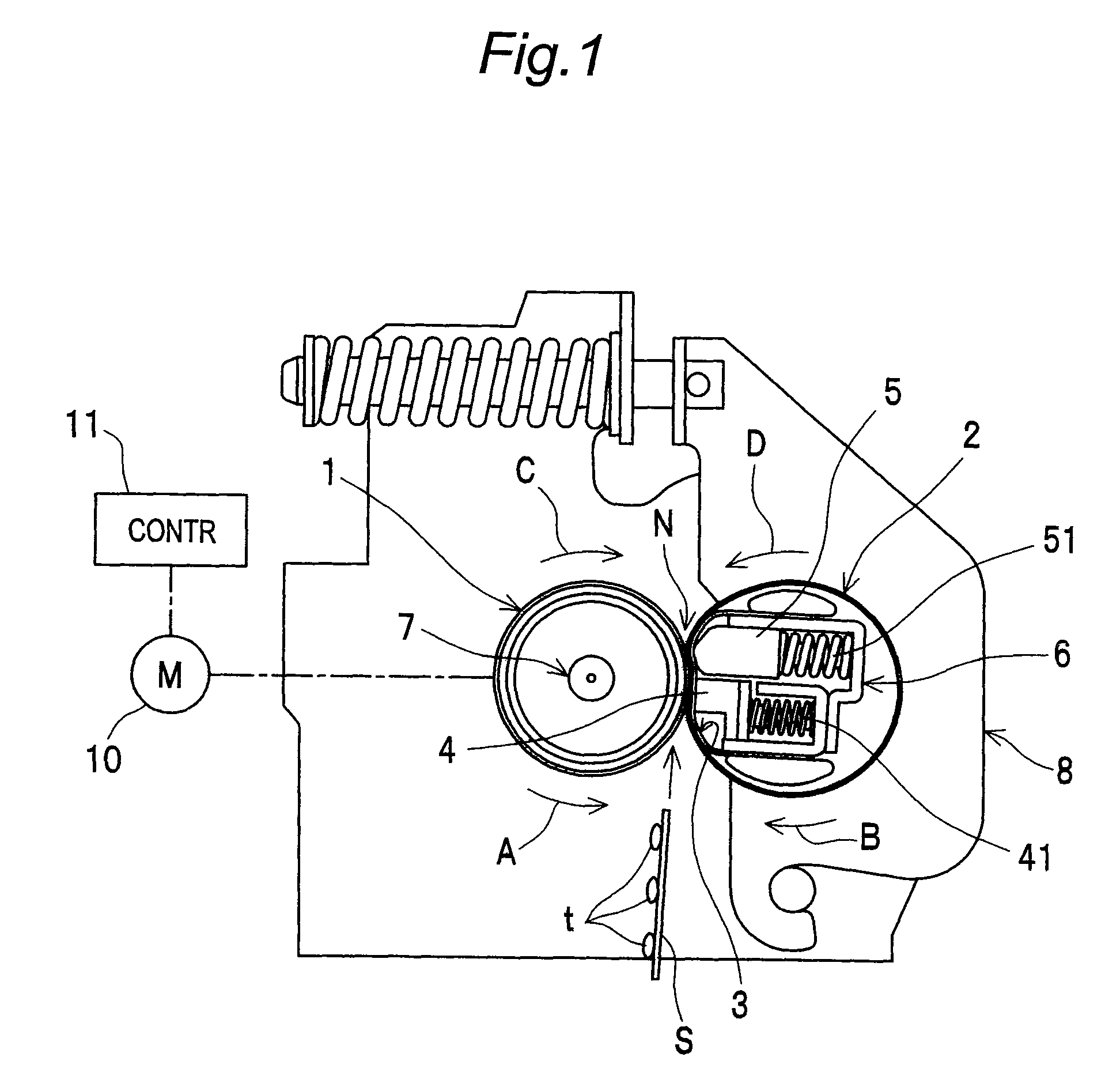
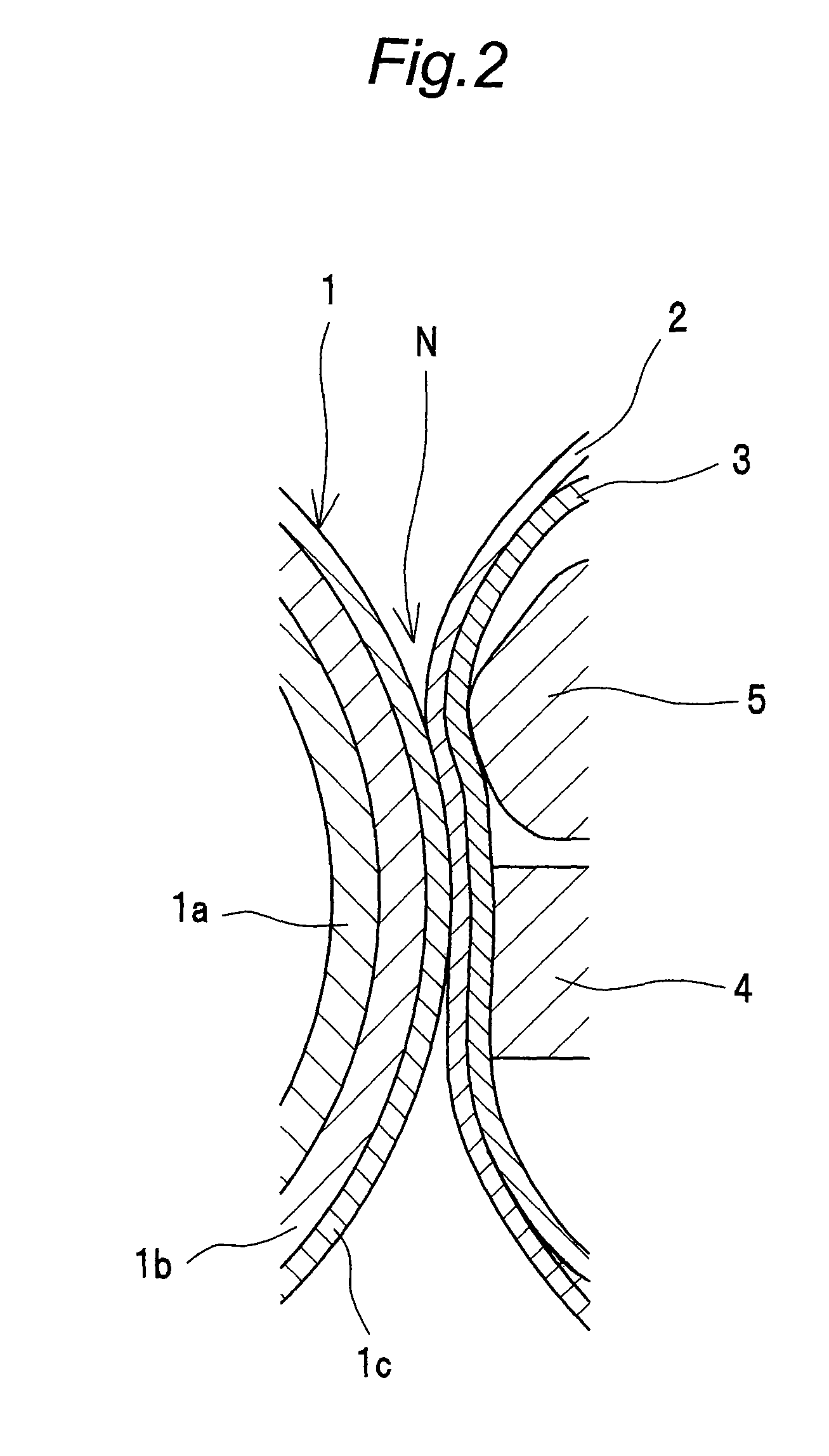
[0030]FIG. 1 shows a schematic structural view of a fixing device according to a first embodiment of the present invention. FIG. 2 shows an enlarged sectional view of a nip portion. The fixing device is used for an image forming apparatus such as a copying machine, a printer or a facsimile.

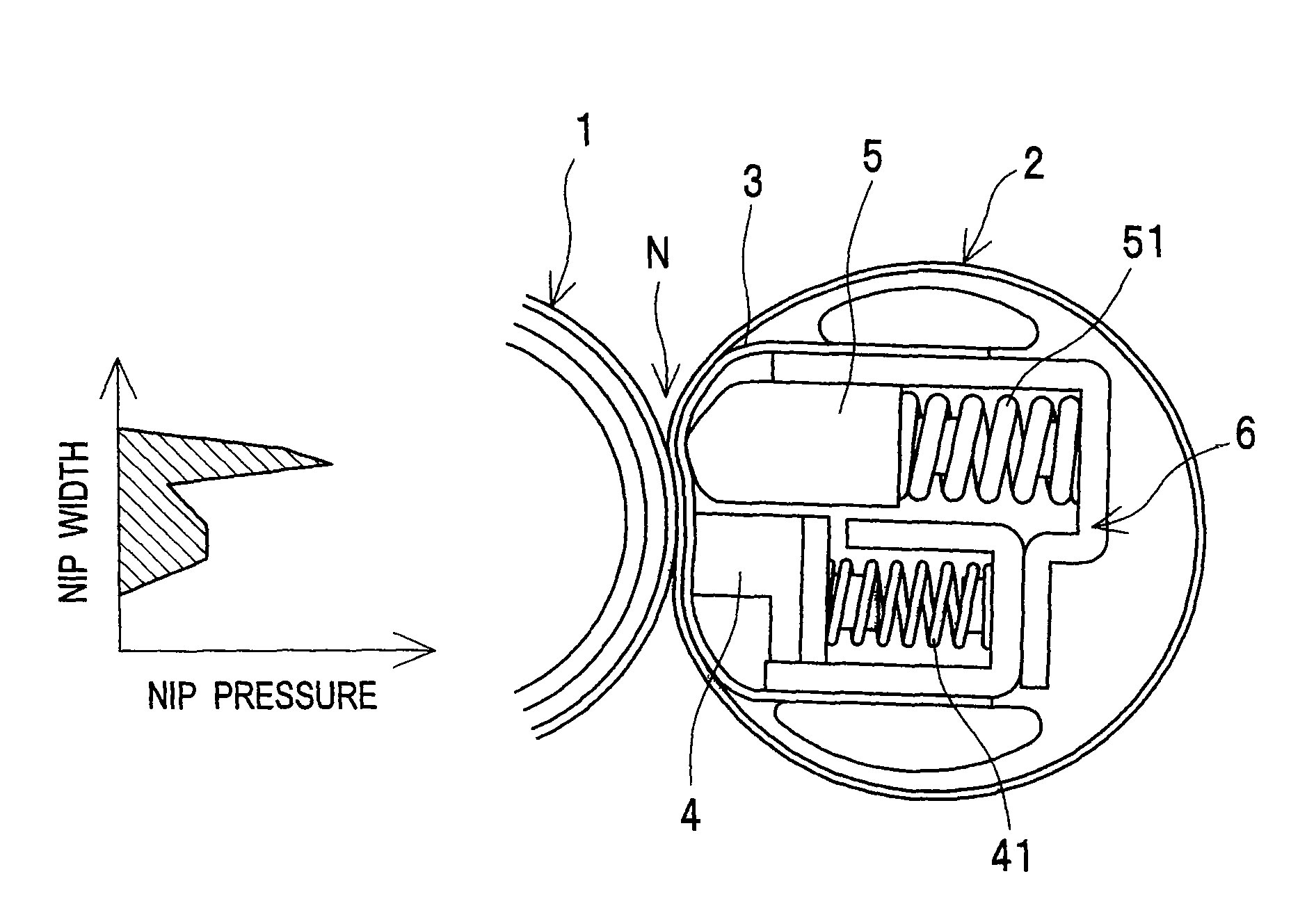
[0031]The fixing device has a heating roller 1 and an endless pressure belt 2. The heating roller 1 is served as a heating rotation unit. The endless pressure belt 2 is brought in external contact with the heating roller 1 and rotated to follow the rotation of the heating roller 1. A nip portion N is formed between the heating roller 1 and the pressure belt 2.

[0032]The heating roller 1 is heated by a halogen lamp 7 placed inside as a heat source, and the heating roller 1 is rotated by a motor 10 as a driving source. The motor 10 is controlled by a control unit 11.

[0033]Inside the pressure belt 2, a first pressurizing member 4 and a second pressurizing member 5 are arranged side by side in the rota...

second embodiment

[0064]FIG. 7 shows the fixing device according to a second embodiment of the present invention. The fixing device of the second embodiment is structurally different from the first embodiment (FIG. 1) in a point that the pressure contact force between the heating roller 1 and the pressure belt 2 can be switched from one stage to another stage. Since the other structures than the above are the same as those of the first embodiment, no description is provided therefor.

[0065]That is, in the present second embodiment, it is possible to switch over between a pressure contact state in a normal fixing mode as shown in FIG. 7 and a pressure contact state in an envelope fixing mode as shown in FIG. 8. In the normal fixing mode, a paper sheet such as a plain-paper or a thick paper, which does not easily wrinkle, is fixed as the recording material S. In the envelope fixing mode, a paper sheet such as an envelope, which easily wrinkles, is fixed as the recording material S. More specifically, th...


PUM


Abstract

A fixing device has a heating rotor, a pressure belt, a sheet member, first and second pressurizing members, a motor and a control unit. The control unit controls the motor to rotate the heating rotor and the pressure belt in a direction opposite to a conveyance direction of a recording material at startup time after jam treatment of the recording material. Contact positions of the sheet member with respect to the first and second pressurizing members are changed, so that the sheet member is prevented from obstructing independent actions of each of the first and second pressurizing members, which allows the nip portion N to maintain proper nip width and proper nip pressure. Thus, the fixing device has excellent stability at the nip portion to improve fixability and conveyability of the recording material with a simple construction.

Description

CROSS-REFERENCE TO RELATED APPLICATION[0001]This application is based on application No. 2007-049277 filed in Japan, the entire content of which is hereby incorporated by reference.BACKGROUND OF THE INVENTION[0002]The present invention relates to a fixing device for use in an image forming apparatus such as a copying machine, a printer or a facsimile.[0003]Conventionally, there has been a fixing device including a pivotable fixing roller, an endless belt, a first pressure pad, a second pressure pad, and a low friction sheet, wherein the endless belt moves while forming a nip portion in pressure contact with the fixing roller, wherein the first and second pressure pads are placed inside the endless belt and bring the endless belt in pressure contact with the fixing roller at the nip portion, and wherein the low friction sheet is provided between the endless belt and the first and second pressure pads (JP 2005-148618A).[0004]However, the first and second pressure pads have a construct...

Claims


Application Information

Patent Timeline
Patent Type & Authority Patents(United States)
IPC IPC(8): G03G15/20
CPCG03G15/2039G03G15/50
Inventor FUJIMOTO, YOSHIHISA
Owner KONICA MINOLTA BUSINESS TECH INC
Why Eureka
Try Eureka