Electromechanical transducer and manufacturing method therefor

a technology of electromechanical transducers and manufacturing methods, applied in the direction of electrical transducers, electrostatic generators/motors, mechanical vibration separation, etc., can solve the problems of difficult to put a circuit operating with such a high voltage to practical use, unfavorable influences on human bodies,

Inactive Publication Date: 2013-02-12
CANON KK
View PDF15 Cites 12 Cited by
  • Summary
  • Abstract
  • Description
  • Claims
  • Application Information

AI Technical Summary

Benefits of technology

[0017]The present invention has an object to provide an electromechanical transducer and a method for manufacturing the same. In view of the above-mentioned problems, when the transducer is made to operate in a collapse mode, the state of contact between a vibration membrane and a substrate provided with a lower electrode can be kept without applying an external force thereto, thereby making it possible to perform voltage reduction in a stable manner.
[0018]Also, in view of the above-mentioned problems, the present invention has another object to provide an electromechanical transducer and a method for manufacturing the same which can be driven in a more stable manner in a state in which a DC voltage to be applied is more reduced even in a conventional mode.
[0032]According to the present invention, it is possible to achieve an electromechanical transducer and a method for manufacturing the same in which when the transducer is made to operate in a collapse mode, the state of contact between a vibration membrane and a substrate provided with a lower electrode can be kept without application of an external force, thereby making it possible to perform voltage reduction in a stable manner.
[0033]In addition, according to the present invention, it is possible to achieve an electromechanical transducer and a method for manufacturing the same which can be driven in a more stable manner in a state in which a DC voltage to be applied is more reduced even in a conventional mode.

Problems solved by technology

However, the application of such a high voltage also poses a problem in putting the formation of a surface insulation film on the transducer into practical use so as to avoid resultant adverse effects.
In case where the CMUT with such a high voltage applied thereto is used for acoustic diagnostics, an unfavorable influence might be caused on human bodies.
However, it is extremely difficult to put a circuit operating with such a high voltage to practical use, and in case where the CMUT, being operated with such a high voltage, is used for acoustic diagnostics, unfavorable influences might be exerted on human bodies.
Moreover, if such a high voltage is applied, the vibration membrane might cause dielectric breakdown, thereby making the lower electrode and the upper electrode be short-circuited to each other.
Therefore, as referred to above, there arise problems such as circuit construction, influences on human bodies, a short-circuit between a lower electrode and an upper electrode, etc.
Further, even in the above-mentioned examples that have been proposed for coping with these problems, the following unfavorable influences are given to the vibration mass, the rigidity, the stability, etc., of the vibration membrane.
For instance, in Japanese patent application laid-open No. 2005-27186 in which the lowering of the voltage is intended by the vibration membrane being attracted with the use of the magnet, not only deposition and magnetization of a magnetic material on an upper portion (or an internal portion or a lower portion) of the vibration membrane become necessary, but also a magnetic field forming means is required for the underlayer substrate, resulting in a complicated structure.
In addition, there is also a problem in that an amount of initial displacement of the vibration membrane is attracted by the magnetic field, and hence is liable to be influenced by external magnetic fields and external disturbances.
That is, the amount of electrification by an electrical discharge is liable to be influenced by environmental factors such as humidity, dielectric substances, etc., and the amount of electrification in the vibration membrane and the amount of initial displacement thereof are unstable, and variation between elements is large.
Accordingly, this can not be called operating in a collapse mode in a strict meaning, but if this is converted into a collapse mode, there will be the following problems.
That is, in case where the deformed shape of the vibration membrane is kept by such hardening of the resist, the shape of the vibration membrane is changed and is made unstable due to a change over time of the resist, and / or a temperature-related change in property or quality thereof.
In addition, because the resist covers an outer periphery of the vibration membrane, there is also another problem that an effective area (filling factor) receiving an ultrasonic wave is decreased.

Method used


Image

  • Electromechanical transducer and manufacturing method therefor
  • Electromechanical transducer and manufacturing method therefor
  • Electromechanical transducer and manufacturing method therefor

Examples


embodiment 1

[0047]Now, reference will be made to a capacitive micromachined ultrasonic transducer (CMUT) according to a first embodiment of the present invention.

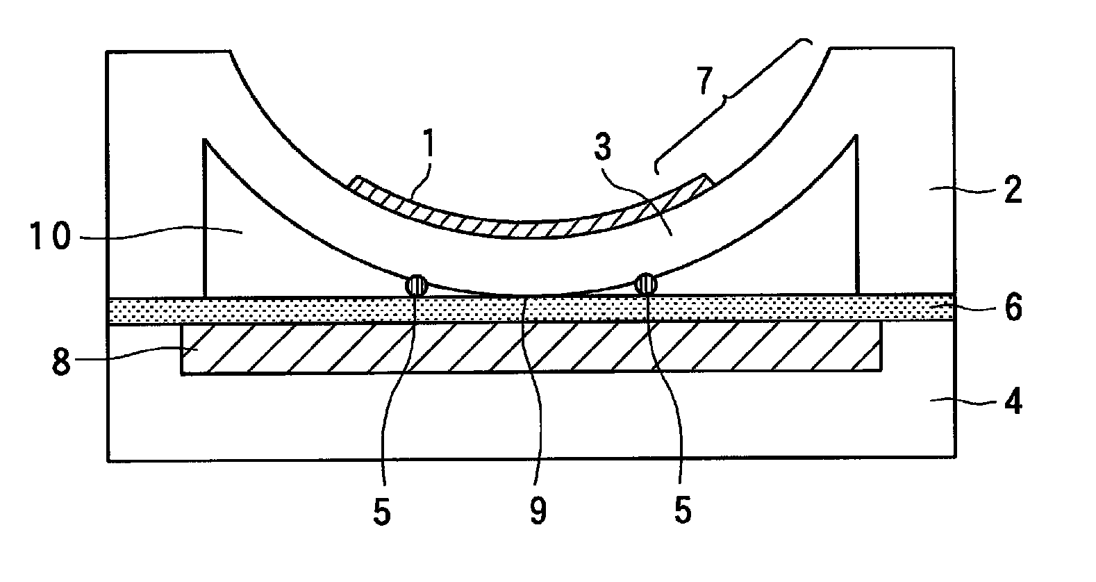
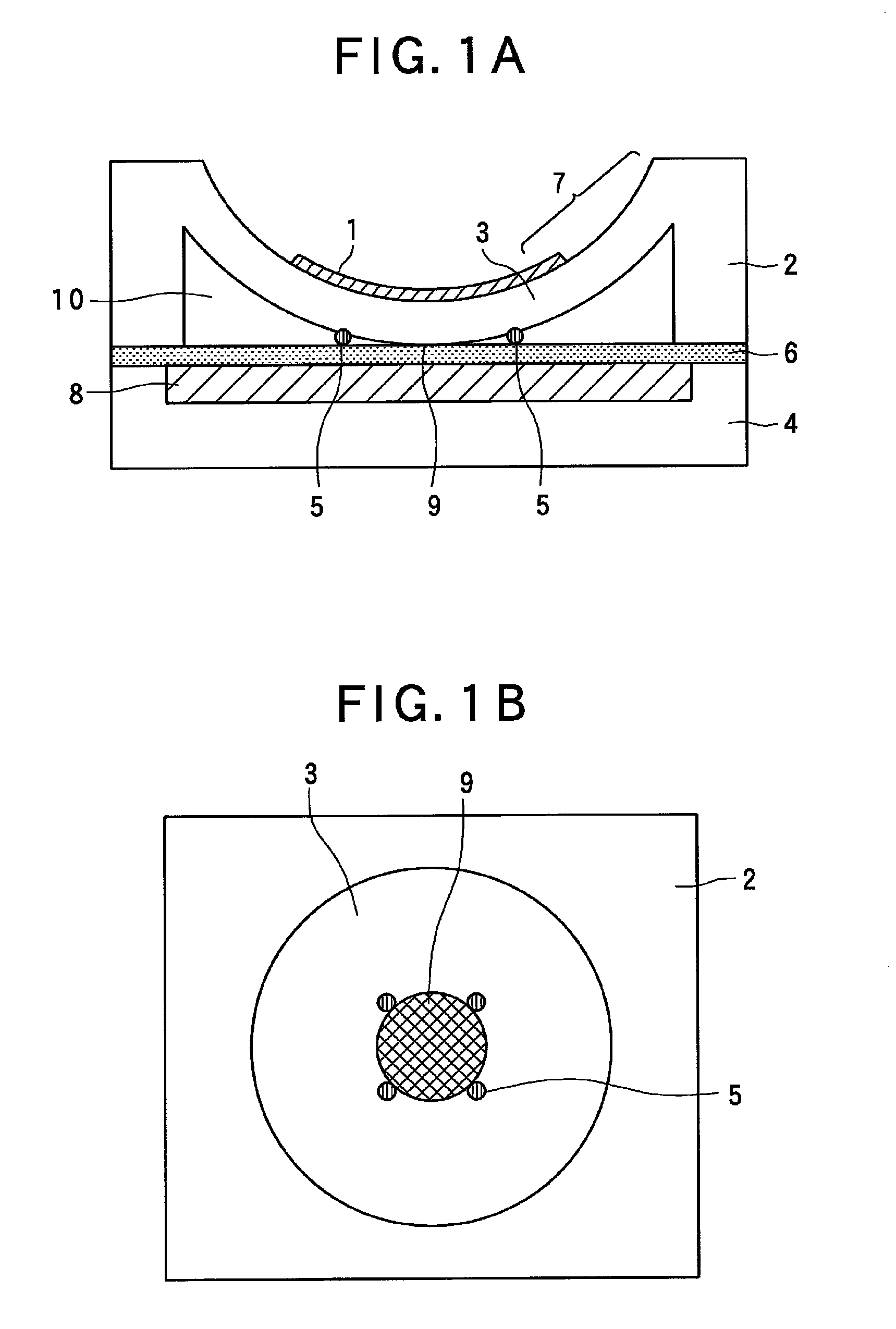
[0048]FIG. 1A and FIG. 1B are views illustrating a basic construction of a capacitive micromachined ultrasonic transducer (CMUT) in the first embodiment of the present invention. FIG. 1A is a conceptual cross sectional view of the capacitive micromachined ultrasonic transducer (CMUT), and FIG. 1B is a conceptual plan view of the capacitive micromachined ultrasonic transducer (CMUT).

[0049]In FIG. 1A and FIG. 1B, 1 designates an upper electrode which is a first electrode, 2 a vibration membrane support member, 3 a vibration membrane, 4 a substrate, 5 protrusions, 6 an insulation film, 7 an outer peripheral portion of the vibration membrane, 8 a lower electrode which is a second electrode, 9 a contact region (fusion bonded region), and 10 a cavity.

[0050]The CMUT of this embodiment includes, as shown in FIG. 1A, the vibration membrane 3 pr...

embodiment 2

[0099]Hereinafter, reference will be made to a capacitive micromachined ultrasonic transducer (CMUT) in a second embodiment of the present invention.

[0100]FIG. 3 is a view illustrating the basic construction of the capacitive micromachined ultrasonic transducer (CMUT) in the second embodiment. Also, in FIG. 4, there is shown a conceptual plan view of this capacitive micromachined ultrasonic transducer (CMUT).

[0101]In the CMUT of this second embodiment, the difference thereof with respect to the CMUT in the first embodiment of the present invention as shown in FIG. 1A and FIG. 1B is that protrusions 5 are formed on an upper portion of a vibration membrane 3 so as to be distributed in a substantially ring-shaped manner, and that a lower electrode 8 is embedded or incorporated in an underlayer substrate. Because a basically different construction is only the above-mentioned construction, those components of this second embodiment which correspond to those of the construction of the CMU...

embodiment 3

[0122]Reference will be made to a capacitive micromachined ultrasonic transducer (CMUT) according to a third embodiment of the present invention. FIG. 6 is a conceptual cross sectional view illustrating a basic construction of the capacitive micromachined ultrasonic transducer (CMUT) in the third embodiment of the present invention. In FIG. 6, 1 designates an upper electrode which is a first electrode, 2 a vibration membrane support member, 3 a vibration membrane, 4 a substrate, 6 an insulation film, 8 a lower electrode which is a second electrode, and 10 a cavity which is a gap.

[0123]The CMUT of this embodiment includes, as shown in FIG. 6, the vibration membrane 3 provided with the upper electrode 1, the substrate 4 provided with the lower electrode 8, and the vibration membrane support member 2 that serves to support the vibration membrane so as to form the gap 10 between the vibration membrane and the substrate with these electrodes being arranged in opposition to each other. He...


PUM

PropertyMeasurementUnit
heightaaaaaaaaaa
DC voltageaaaaaaaaaa

Abstract

In an electromechanical transducer which includes a vibration membrane provided with an upper electrode, a substrate provided with a lower electrode, and a support member adapted to support the vibration membrane in such a manner that a gap is formed between the vibration membrane and the substrate with these electrodes being arranged in opposition to each other, it is constructed such that a part of the vibration membrane and a region of the substrate are kept in contact with each other without application of an external force, and a remaining region of the vibration membrane other than its region in which the contact state is kept is able to vibrate.

Description

TECHNICAL FIELD[0001]The present invention relates to an electromechanical transducer and a method for manufacturing the same. The electromechanical transducer of the present invention is an acoustic transducer of a capacitive type particularly suitable for transmission or reception of an ultrasonic wave.BACKGROUND ART[0002]In recent years, there have been actively researched or studied capacitive ultrasonic transducers using micromachining processes (CMUT; Capacitive Micromachined Ultrasonic Transducer). Hereinafter, such a capacitive ultrasonic transducer is referred to as a CMUT. According to such a CMUT, there can be easily obtained a broadband characteristic that is excellent both in a liquid and in an air by transmitting and receiving an ultrasonic wave by the use of a vibration membrane. Therefore, with ultrasonic diagnostics using this CMUT, it becomes possible to make an ultrasonic diagnosis with higher precision than with a conventional medical diagnostic modality, and hen...

Claims


Application Information

Patent Timeline
Patent Type & Authority Patents(United States)
IPC IPC(8): H04R31/00H02N1/00
CPCB06B1/0292Y10T29/49005
Inventor CHANG, CHIENLIU
Owner CANON KK
Why Eureka
Try Eureka