Portable electronic device and capsule endoscope diagnosis system

a technology of electronic devices and endoscopes, which is applied in the direction of cell components, electrical apparatus casings/cabinets/drawers, instruments, etc., can solve problems such as drawbacks in configuration, and achieve the effect of reliable realization

Active Publication Date: 2013-02-12
OLYMPUS CORP
View PDF30 Cites 4 Cited by
  • Summary
  • Abstract
  • Description
  • Claims
  • Application Information

AI Technical Summary

Benefits of technology

[0027]In the portable electronic device according to the present invention, guide parts are provided on both side walls of a battery housing. A long member is set so as to cross the battery housing in a stretched state by the guide parts in a position where the battery can be taken out by drawing the long member. With the configuration, at the time of loading a battery, by making the long member extend outside, the long member is not entirely housed in the battery housing or absence of the long member in the battery housing can be prevented. By making the battery front end face come into contact with the stretched long member and inserting a battery, a normal loading state in which the long member is pushed to the deepest place can be assured. An effect such that the battery ejecting function with a simple long member can be reliably realized is produced.

Problems solved by technology

However, such a configuration has a drawback.

Method used


Image

  • Portable electronic device and capsule endoscope diagnosis system
  • Portable electronic device and capsule endoscope diagnosis system
  • Portable electronic device and capsule endoscope diagnosis system

Examples


Embodiment Construction

[0074]Preferred embodiments of the present invention will be described in detail hereinbelow with reference to the appended drawings. An example of applying a portable electronic device of an embodiment to a portable receiver carried by the subject and recording data during diagnosis in a capsule endoscope diagnosis system will be described.

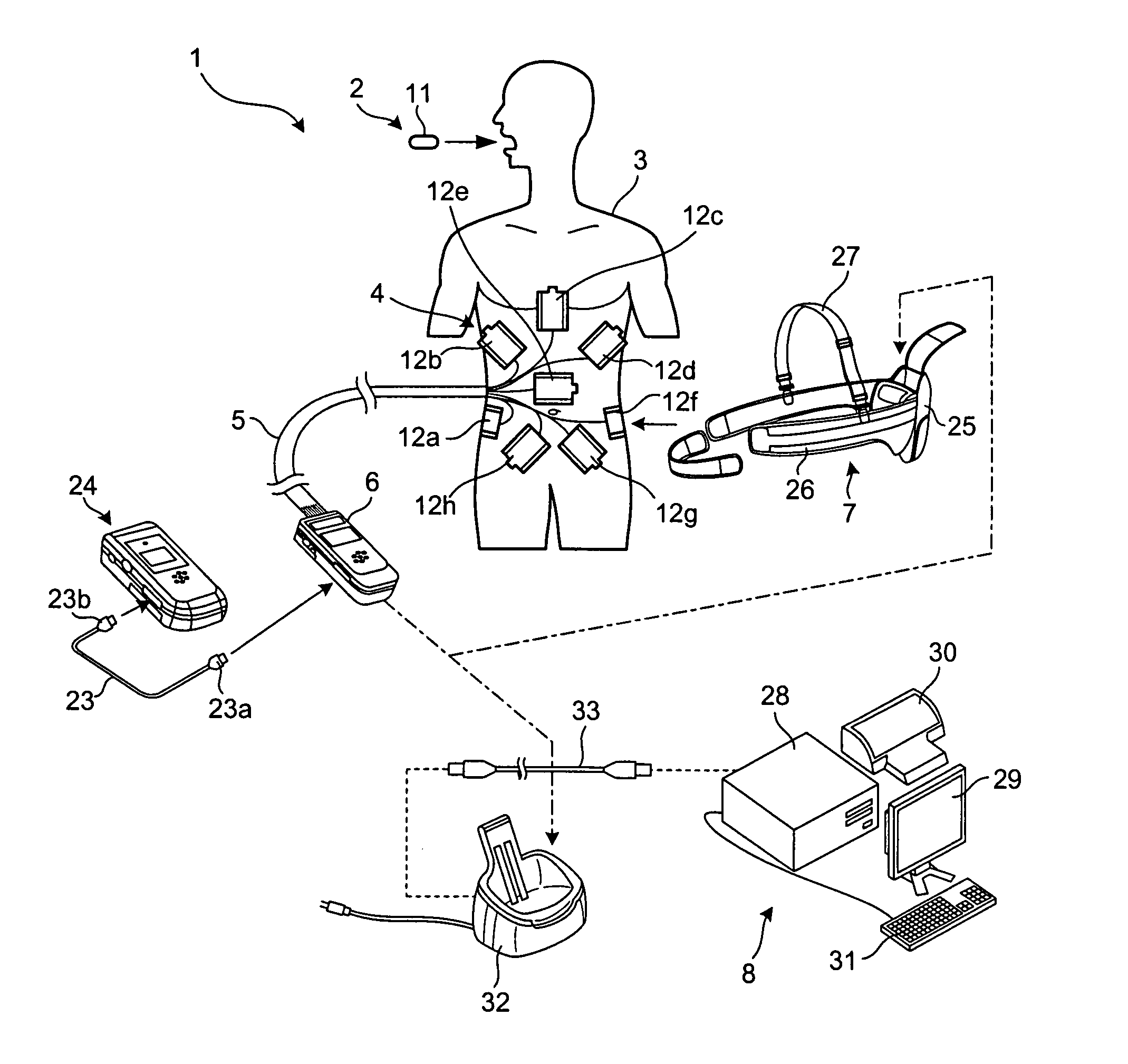
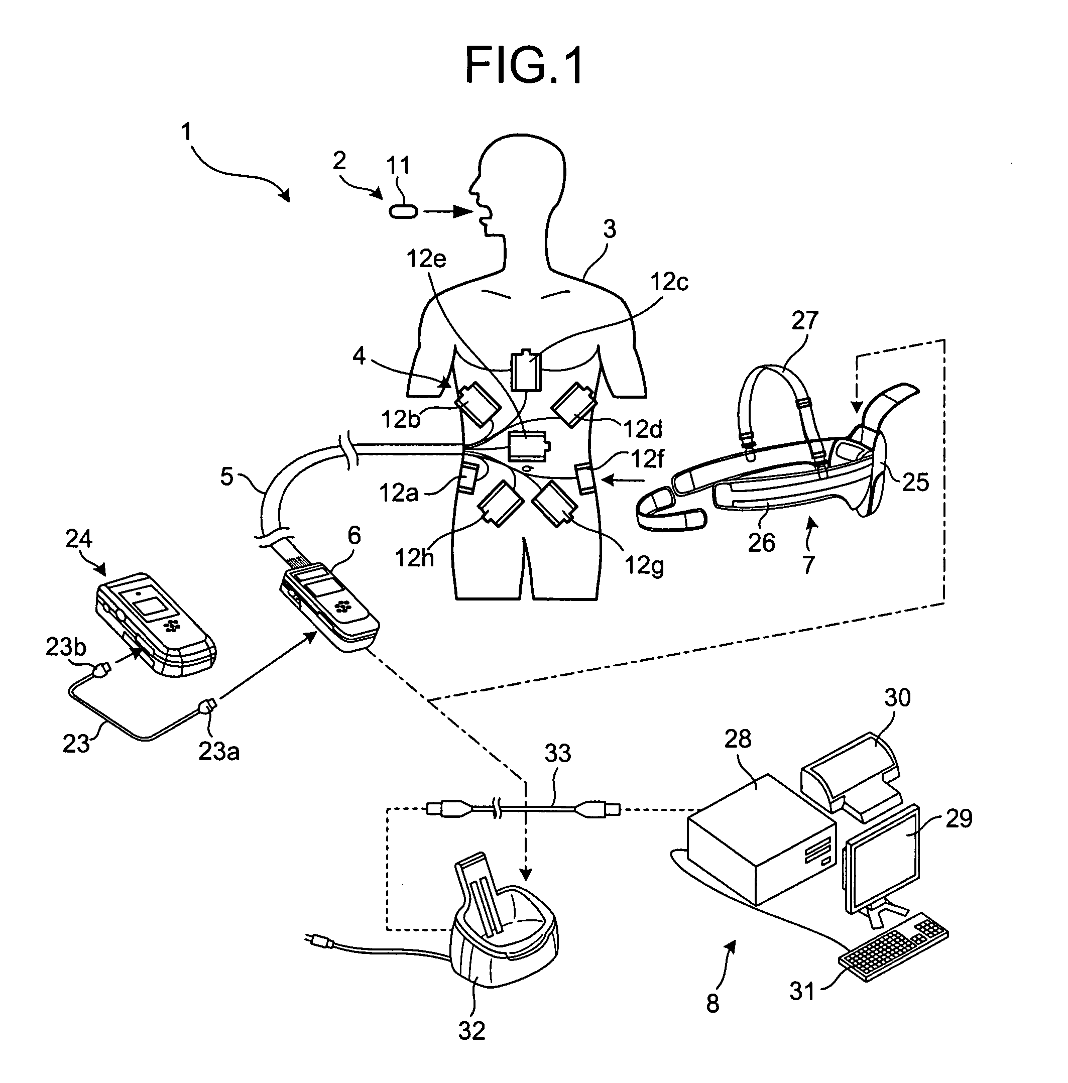
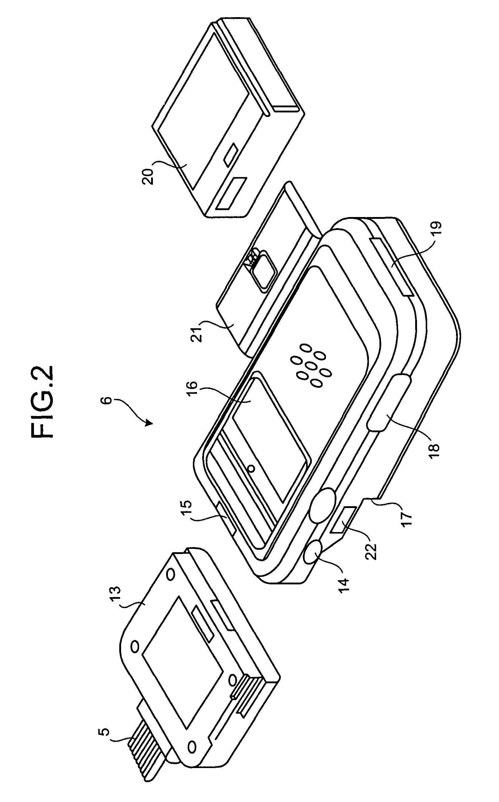
[0075]FIG. 1 is a diagram showing a general configuration of a capsule endoscope diagnosis system including a portable receiver according to an embodiment the invention. FIG. 2 is a perspective diagram showing an antenna jack and a receiver. A capsule endoscope diagnosis system 1 is mainly constructed by a capsule endoscope 2, a detector 4 having a loop antenna structure which is directly attached to a predetermined region on the surface of the body of a subject 3 by adhesion or the like, a portable receiver 6 as a portable electronic device electrically connected to the detector 4 via a cable 5 and recording a detection result, a receiver holder...


PUM

PropertyMeasurementUnit
lengthaaaaaaaaaa
biasing forceaaaaaaaaaa
tensile stressaaaaaaaaaa

Abstract

The present invention is directed to reliably prevent a trouble that a battery is loaded either in a state where a ribbon is entirely housed in a battery housing or without a ribbon by a simple method using a ribbon. Guide parts (83, 84) are provided on both side walls (57, 58) of a battery housing (53). A ribbon (81) is set so as to cross the battery housing (53) in a stretched state by the guide parts (83, 84) in a position where the battery can be taken out by drawing the ribbon (81). With the configuration, at the time of loading a battery, by making the ribbon (81) extend outside, the ribbon (81) is not entirely housed in the battery housing (53) or absence of the ribbon (81) in the battery housing (53) can be prevented. By making the battery front end face come into contact with the stretched ribbon (81) and inserting a battery, a normal loading state in which the ribbon (81) is pushed to the deepest place can be assured. The battery ejecting function with a simple ribbon (81) can be reliably displayed.

Description

TECHNICAL FIELD[0001]The present invention relates to a portable electronic device and a capsule endoscope diagnosis system.BACKGROUND ART[0002]Generally, in various portable electronic devices, a battery as a power source has to be exchangeably loaded. As a well-known technique, there is a portable electronic device having a configuration such that a battery is loaded so as to be placed on a ribbon whose one end is fixed and which is arranged in a battery housing and, at the time of exchanging the battery, the battery is taken out from the battery housing by drawing a free end of the ribbon. The configuration is employed because the ribbon constructed by a bias fabric made of polyester fibers or the like has high tensile stress, and both ends of the ribbon do not fray.[0003]However, such a configuration has a drawback. In the case where the battery is loaded in a state where the ribbon is placed in an unexpected position such as a buried state where the whole ribbon including the f...

Claims


Application Information

Patent Timeline
Patent Type & Authority Patents(United States)
IPC IPC(8): A61B1/04H01M2/10H05K7/00H05K5/00G06F1/16H01M50/209
CPCA61B1/04H01M2/1066A61B1/041A61B2017/00734Y02E60/10H01M50/209
Inventor AKAGI, TOSHIMASA
Owner OLYMPUS CORP
Why Eureka
Try Eureka