Conveying Device Drivable By Rack Gear

a technology of conveyors and gears, applied in mechanical conveyors, friction gearings, gearings, etc., can solve problems such as gear tooth breakage or other problems

Active Publication Date: 2017-06-01
DAIFUKU CO LTD
View PDF10 Cites 3 Cited by
  • Summary
  • Abstract
  • Description
  • Claims
  • Application Information

AI Technical Summary

Problems solved by technology

When such a situation occurs, the first gear tooth at the rear side of the tooth lacking portion becomes inca...

Method used


Image

  • Conveying Device Drivable By Rack Gear
  • Conveying Device Drivable By Rack Gear
  • Conveying Device Drivable By Rack Gear

Examples


Embodiment Construction

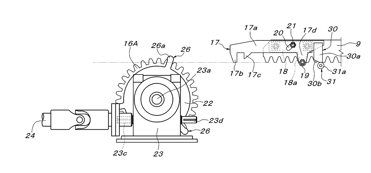
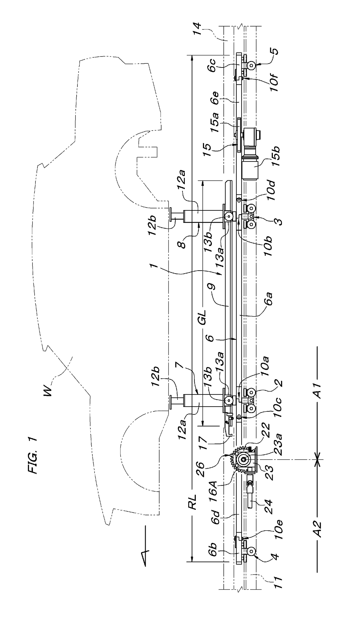
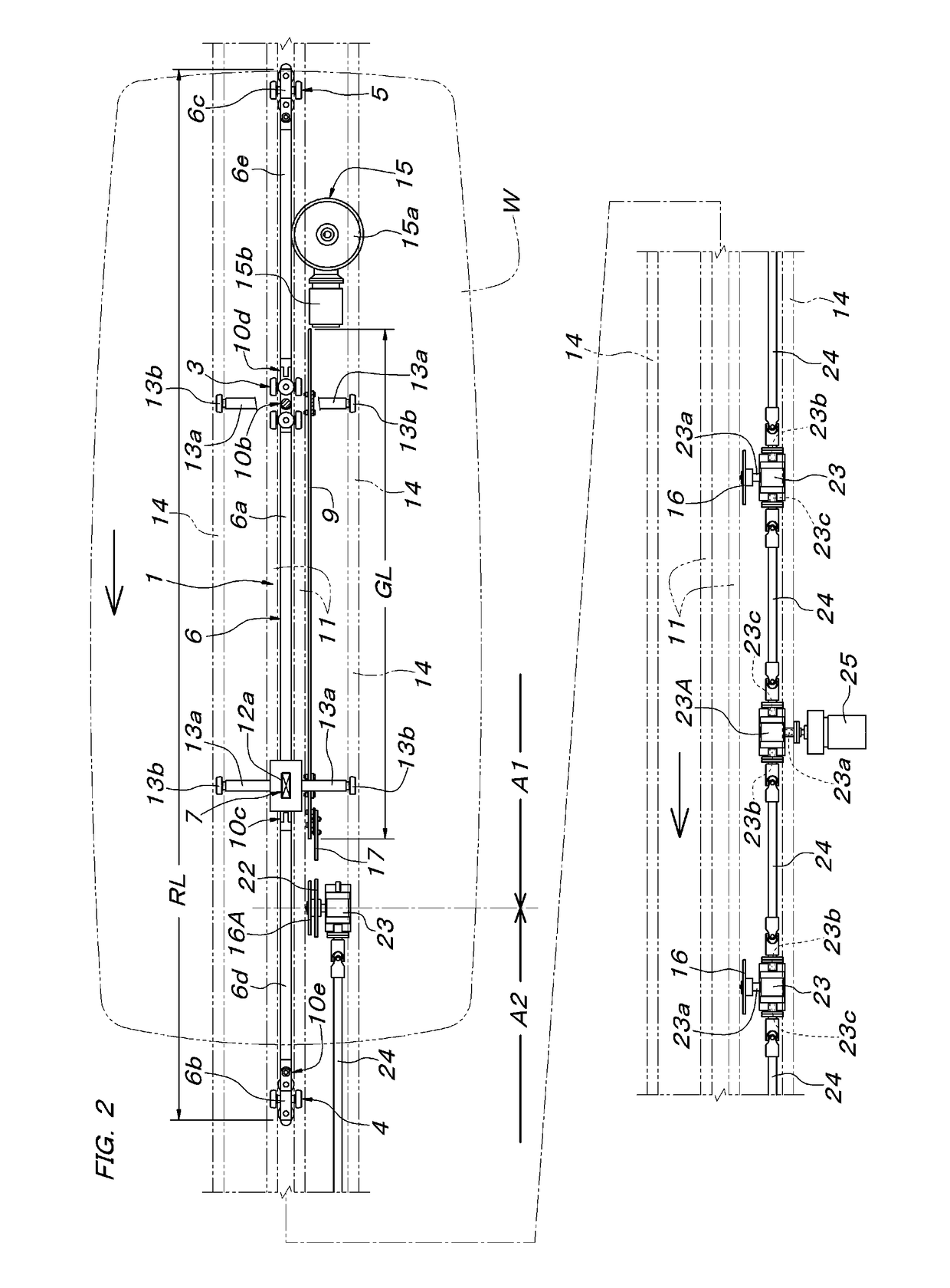
[0019]In FIG. 1 to FIG. 3B, 1 is a conveying traveling body and is constituted from four trolleys 2 to 5, a load bar 6 of total length RL supported by the trolleys 2 to 5, a pair of front and rear conveyed object supporting bodies 7 and 8 supported by the load bar 6, and a rack gear 9. The load bar 6 is constituted from a central load bar unit 6a coupling together the pair of front and rear load trolleys 2 and 3, which are positioned at a middle among the trolleys 2 to 5, respective front and rear end load bar units 6b and 6c supported by the free trolleys 4 and 5 at respective front and rear ends, and a pair of front and rear coupling load bar units 6d and 6e coupling the central load bar unit 6a and the respective front and rear end load bar units 6b and 6c, and a side surface that is continuous across the total length is configured as a friction surface for friction drive.

[0020]Also, respectively between the central load bar unit 6a and the coupling load bar units 6d and 6e are i...


PUM


Abstract

A conveying device drivable by rack gear has a towed hook further forward than a front end of a rack gear mounted to a conveying traveling body. A driving pinion gear, disposed at an entrance of a rack gear drive section, has a drawing-in claw that engages the towed hook and draws in the conveying traveling body to a position where the front end of the rack gear meshes with the driving pinion gear. The towed hook has, at a position at a rear side of a hook portion at a distal end thereof and further forward than the front end of the rack gear, an advance preventing claw portion disposed continuous thereto that, together with the hook portion, sandwiches the drawing-in claw, and the hook portion has a length such that it enters more deeply inside a rotation locus of the drawing-in claw than the advance preventing claw portion.

Description

FIELD OF THE INVENTION[0001]The present invention relates to a conveying device drivable by rack gear with which a conveying traveling body can be driven to travel, just within a specific section in a traveling route of the conveying traveling body, by a rack gear, mounted to the conveying traveling body, and a driving pinion gear, provided at the traveling route side so as to mesh with the rack gear.BACKGROUND OF THE INVENTION[0002]As examples of this type of conveying device drivable by rack gear, conveying devices described in Japanese Published Unexamined Patent Application No. H8-74961 (Patent Literature 1) and Japanese Published Unexamined Patent Application No. 2006-38190 (Patent Literature 2) are known. The configurations described in Patent Literature 1 and Patent Literature 2 are for making a forwardly moving rack gear mesh smoothly with a driving pinion gear pivotally supported at a fixed position, and with the configuration described in Patent Literature 1, a towed hook ...

Claims


Application Information

Patent Timeline
IPC IPC(8): F16H19/04B65G19/02
CPCF16H19/04F16H2019/046B65G19/02B65G35/00B65G17/12B65G17/005
Inventor SUZUKI, TAKAHARUHIROKARI, YOSHIKAZU
Owner DAIFUKU CO LTD
Why Eureka
Try Eureka