Semiconductor differential amplifier
a technology of differential amplifier and semiconductor, applied in differential amplifiers, amplifier details, amplifiers with semiconductor devices/discharge tubes, etc., can solve problems such as significant problems, stacked transistors cannot be operated in the saturation region, and constraints on the design of analog circuits, so as to achieve high gain operation, reduce the number of stacked transistors, and maximize output amplitude
- Summary
- Abstract
- Description
- Claims
- Application Information
AI Technical Summary
Benefits of technology
Problems solved by technology
Method used
Image
Examples
first embodiment
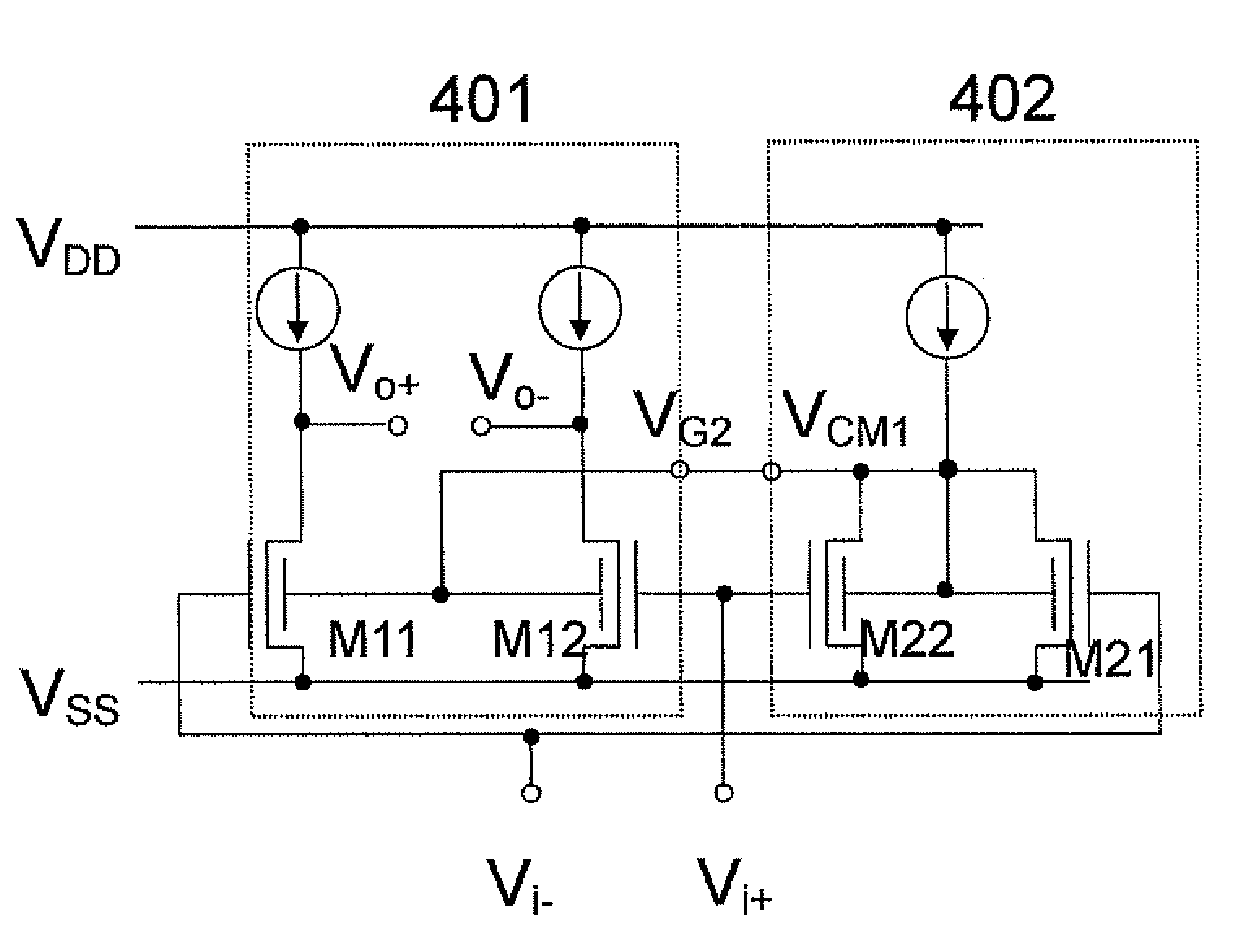
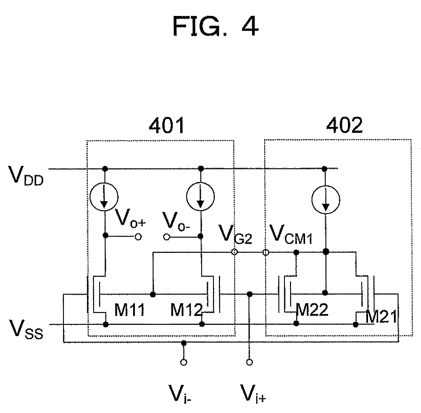
[0036]FIG. 4 shows the most fundamental circuit configuration disclosed in the present invention. In FIG. 4, numeral reference 401 denotes a main body of a differential pair, and 402 denotes an input common-mode component detection circuit. The most fundamental semiconductor differential amplifier is configured by inputting an output voltage VCM1 of the input common-mode signal detection circuit to a terminal VG2 of the differential pair 401.
[0037]Here, n-channel four-terminal fin type FETs M11, M12, M21, and M22 have a device structure as shown by 501 in FIG. 5. Symbols in a circuit diagram of M11, M12, M21 and M22 are shown by 502. These devices are fabricated by separating the usual connected gates of a typical fin type FET into a first gate 503 and a second gate 504. In this description, an input signal is input into the first gate and a signal for controlling the threshold voltage is input into the second gate.
[0038]In FIG. 5, 502 and 511 denote symbols showing an n-channel fou...
second embodiment
[0041]FIG. 6 shows the first embodiment for realizing a current source loads of the input common-mode signal detection circuit 402 and the main body of the differential pair 401 by p-type three-terminal fin type FETs M31, M32 and M4 which are realized by applying a common reference voltage to these p-channel three-terminal fin type FETs in details. However in this embodiment, when an input common-mode signal VCMi becomes too large, VCM1 approaches the ground potential, where the operation for common-mode rejection by M11 and M12 becomes impossible, and M11, M12 start to operate in a linear region.
third embodiment
[0042]A method to solve this problem is shown in FIG. 7. That is, to gates of p-channel four-terminal fin type FETs M31 and M32, a common-mode feedback signal Vcm2 generated by n-channel three-terminal fin type FETs M51, M52 and M53 are input. Therefore, even when the common-mode rejection by M11, M12, M21 and M22 can not be performed, an operation in the saturation region is maintained, and the output common-mode level is kept constant in the main body of the differential pair 401.
PUM
 Abstract
Description
Claims
Application Information
 - R&D
- Intellectual Property
- Life Sciences
- Materials
- Tech Scout
- Unparalleled Data Quality
- Higher Quality Content
- 60% Fewer Hallucinations
Browse by: Latest US Patents, China's latest patents, Technical Efficacy Thesaurus, Application Domain, Technology Topic, Popular Technical Reports.
© 2025 PatSnap. All rights reserved.Legal|Privacy policy|Modern Slavery Act Transparency Statement|Sitemap|About US| Contact US: help@patsnap.com


