Controlled-volume infusion device

a technology of infusion device and controlled volume, which is applied in the direction of flow monitor, intravenous device, medical syringe, etc., can solve the problems of inability to reuse for subsequent dosage, inconvenient use in alternate care sites such as the patient's home, and high cost of electronic pumps

Inactive Publication Date: 2013-02-12
CURLIN MEDICAL INC
View PDF46 Cites 58 Cited by
  • Summary
  • Abstract
  • Description
  • Claims
  • Application Information

AI Technical Summary

Problems solved by technology

The problem with conventional electronic pumps used in this application is that electronic pumps tend to be relatively expensive, complex to use and maintain, and inconvenient for use in alternate care sites such as the patient's home.
The problem with conventional disposable pumps used in this application is that the pumps are designed to dispense a single dose of medication, and cannot be reused for subsequent dosages without risk of contamination.
This requires extra effort by the healthcare provider to prepare multiple pumps, and entails additional expense to purchase multiple pumps.
These devices do not provide a large enough dosage volume to be used for many applications.
However, these electronic pumps tend to be relatively expensive, complex to use and maintain, and inconvenient for use in alternate care sites such as the patient's home.
One problem with currently available disposable PCA devices is that they are not well suited for large bolus dosage volumes.
Larger bolus dosage volumes of 5, 10, or more cc's have been shown to be clinically efficacious, but impractical with currently-available PCA devices.
Manual force from the patient is required to administer the bolus dosage, and larger dosage volumes require greater manual effort; the manual effort that would be required to administer a large bolus dosage can be a burden on patients in a weakened state.
With a large volume dosage, it may take an extended period of time (several minutes to an hour or longer) for the dosage reservoir to empty, and it is not practical for a patient to maintain finger pressure for such an extended period of time.
The practical size of the bolus dosage is also limited by the fact that the bolus is infused over a short period of time (from a few seconds or less up to several minutes), and the amount of fluid the body can absorb in such a short time is very limited.
For example, clinicians treating post-operative pain following orthopedic surgery with a PCA infusion of local anesthetic agent into the surgical site have observed that even a 5-cc bolus dosage often leaks out of the incisions, depriving the patient of the full anesthetic effect of the medication and potentially inhibiting healing of the incision.
Another problem with currently available disposable PCA devices is that they have a bolus reservoir that fills slowly without any patient input.
The problem with this is that if a patient does not need a bolus, the unused medication in the bolus reservoir is wasted.
With expensive medications, this waste is not economical, especially with large bolus sizes.
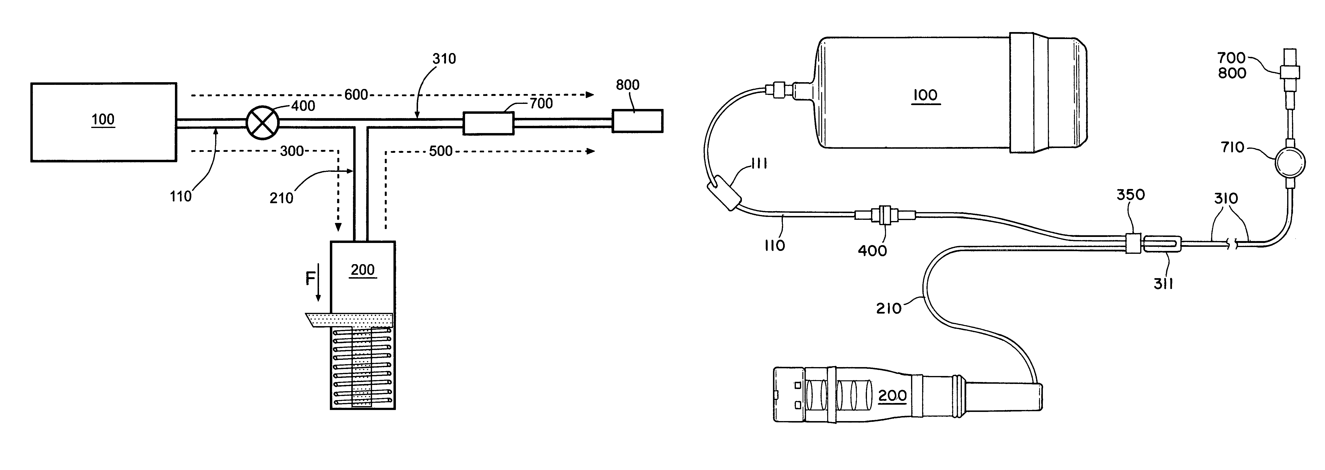
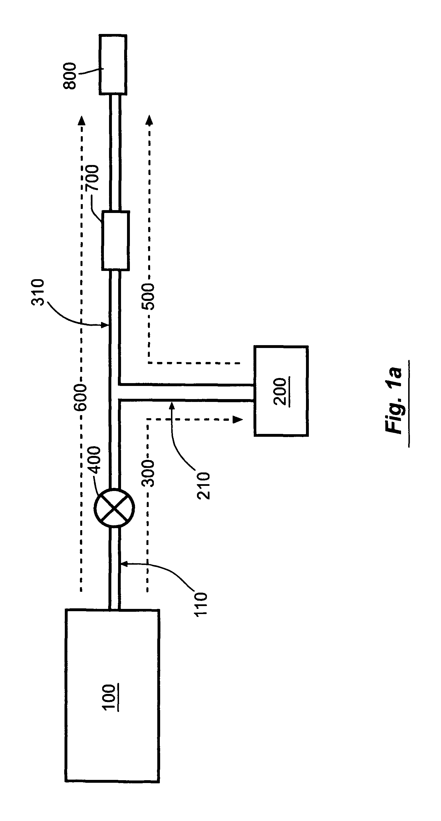
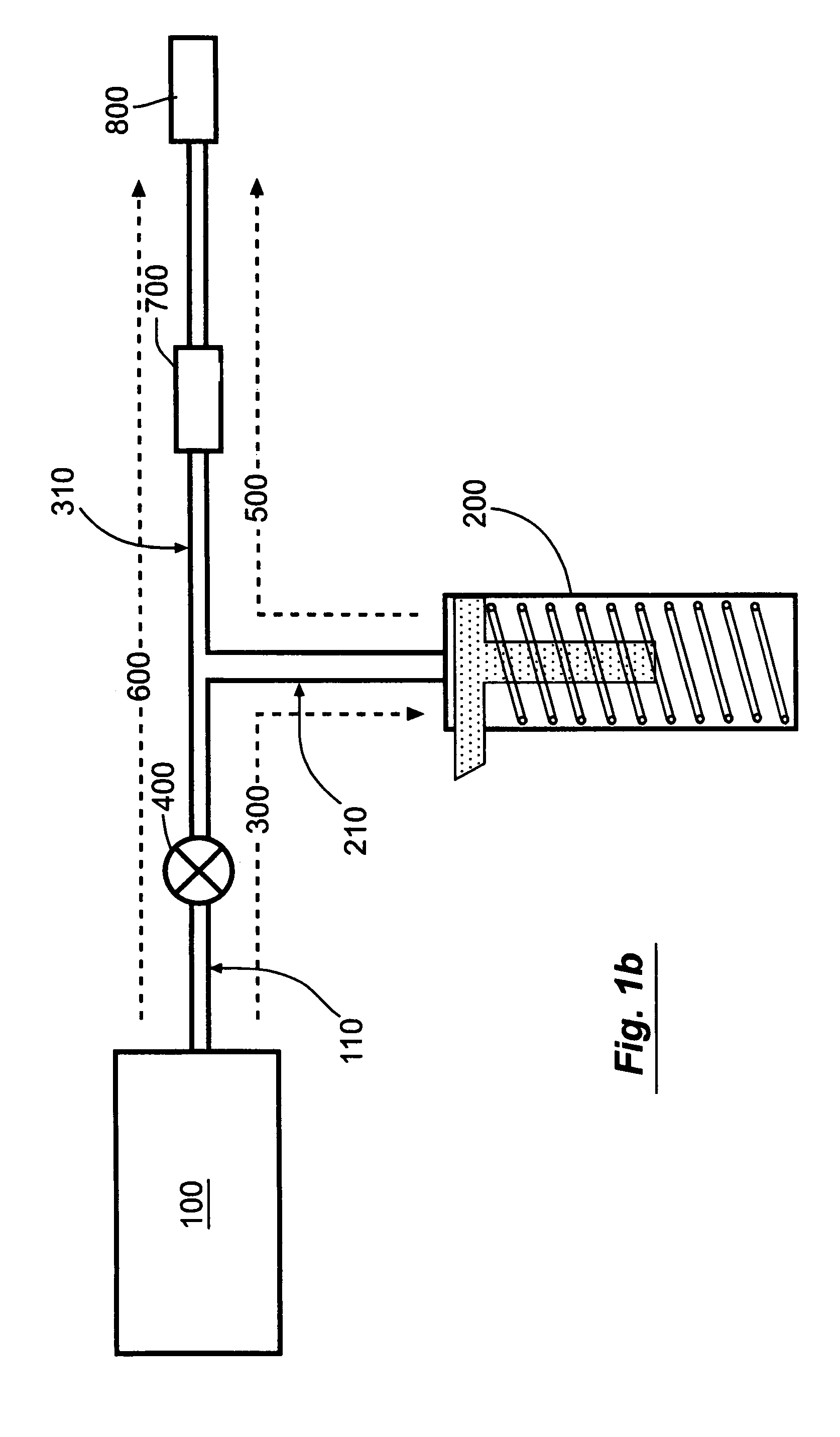
Another problem with those currently available disposable PCA devices that provide basal-bolus infusion is that they have two parallel flow paths, each with their own flow restrictor, and a valve is required immediately downstream of the bolus reservoir.
The use of two flow restrictors and the valve add cost and complexity to the mechanism.
Another problem with currently available disposable PCA devices is that by placing the flow restrictors proximal to the bolus reservoir, the fluid path volume distal to the flow restrictors is relatively large.
Since all segments of the fluid path that are distal to the flow restrictor are primed at the restricted flow rate, these devices take a long time to prime (often in excess of 30-60 minutes).
This long priming time is inconvenient for the clinicians setting up the device, and is not a cost-effective use of nursing time (especially if the device is being used in an operating room, where wasted setup time can results in hundreds of dollars worth of lost productivity in room usage).
A precision flow restrictor is often the costliest component of the device.
A device that requires two flow restrictors for two distinct flow rates may be significantly more costly that a device that needs only one flow restrictor to achieve two distinct flow rates, such as the device described herein.

Method used


Image

  • Controlled-volume infusion device
  • Controlled-volume infusion device
  • Controlled-volume infusion device

Examples


Embodiment Construction

[0058]FIG. 1a shows a schematic view of the “basal-bolus” embodiment of the invention, providing for administration of a series of controlled-volume dosages of medication or other fluid with a continuous flow of fluid between dosages. The device includes a medication reservoir 100 that holds medication or other fluid under substantially constant pressure (the medication reservoir pressure, Pm). When the user actuates the controlled-volume dosage, the medication reservoir pressure causes fluid to be expelled from the medication reservoir 100, and to flow through the first fluid flow path 300 through the source conduit 110 and dosage conduit 210 into the controlled-volume dosage reservoir 200. When the dosage reservoir 200 is filled (as illustrated in FIG. 1c), the fluid within the dosage reservoir 200 is pressurized to a higher substantially constant pressure (the dosage reservoir pressure, Pd, which is not necessarily constant), which is greater than the medication reservoir pressur...


PUM


Abstract

An infusion device capable of administering liquid medication at a continuous flow rate, and upon user demand delivers a controlled volume dosage of liquid medication at a higher dosage flow rate. The dosage reservoir remains empty until the user actuates it by selectively and temporarily removing the pressure source, such as a spring. During actuation, fluid rapidly flows from the medication reservoir to fill the dosage reservoir. After actuation, the pressure source exerts a higher pressure on the dosage reservoir than the medication reservoir pressure, which results in a temporary higher bolus flow rate. Thus, two distinct flow rates are achieved with one flow restrictor element.

Description

RELATED APPLICATION[0001]The present application is based on and claims priority to the Applicants' U.S. Provisional Patent Application 60 / 629,795, entitled “Controlled-Volume Infusion Device,” filed on Nov. 19, 2004.BACKGROUND OF THE INVENTION[0002]1. Field of the Invention[0003]This invention relates generally to the field of infusion pumps. More specifically, this invention relates to an improved device and method for administering a series of controlled-volume dosages of fluid, by themselves or in supplement to a continuous infusion of fluid to deliver a liquid medication to a patient.[0004]2. Prior Art[0005]Infusion pumps have been widely used for many years to administer medications and other fluids to patients. Conventional disposable (single-use) infusion pumps administer a substantially continuous flow of fluid. Examples of such infusion pumps include spring-type and vacuum-type syringe pumps, and balloon-type pumps. Conventional electronic, multiple-use infusion pumps may ...

Claims


Application Information

Patent Timeline
Patent Type & Authority Patents(United States)
IPC IPC(8): A61M5/00
CPCA61M5/1454A61M5/14216A61M5/14586A61M5/16877A61M5/31511A61M5/178A61M5/315
Inventor NEEDLE, STANLEY A.LAMBORNE, ANDREW N.
Owner CURLIN MEDICAL INC
Why Eureka
Try Eureka