

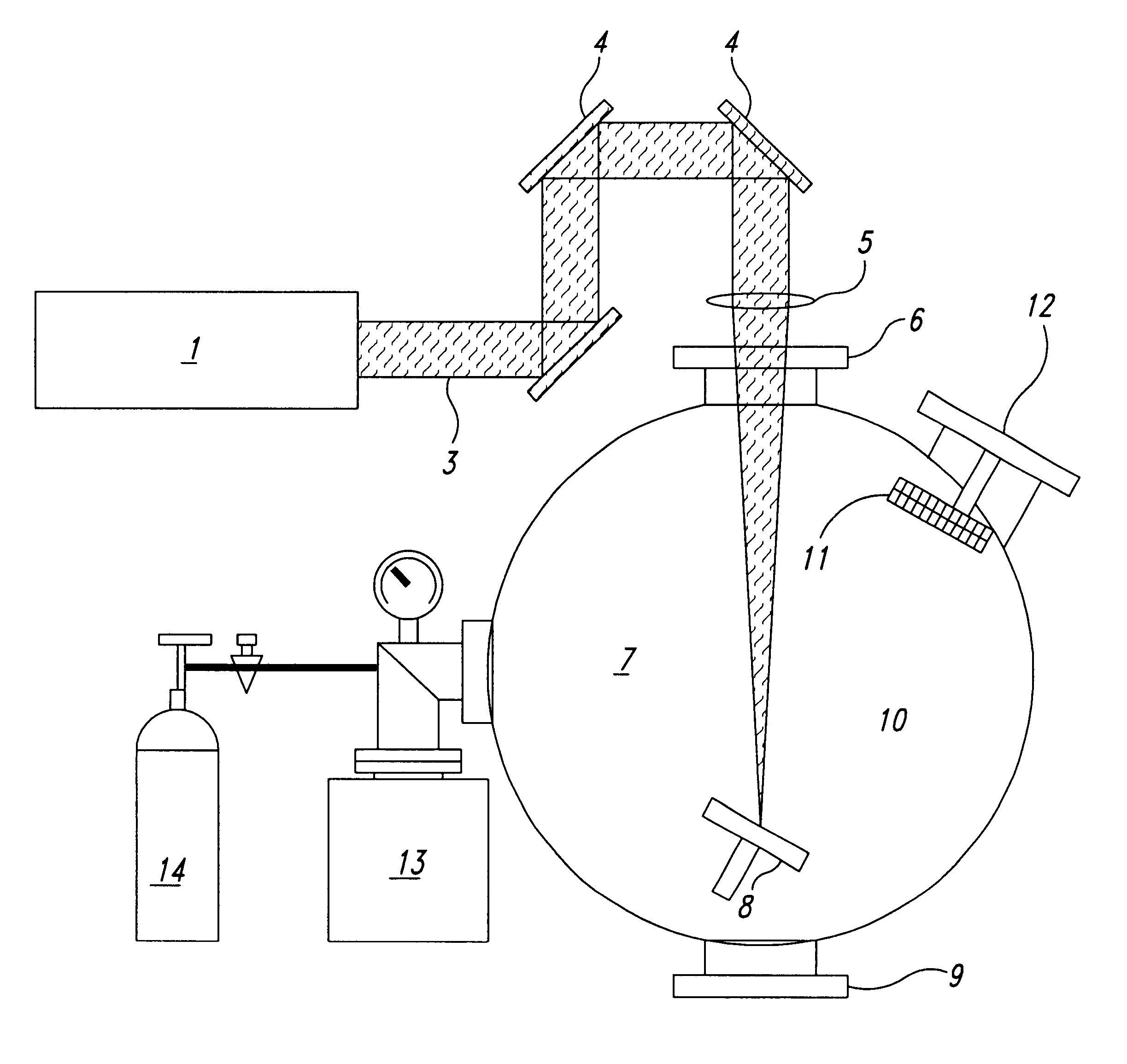
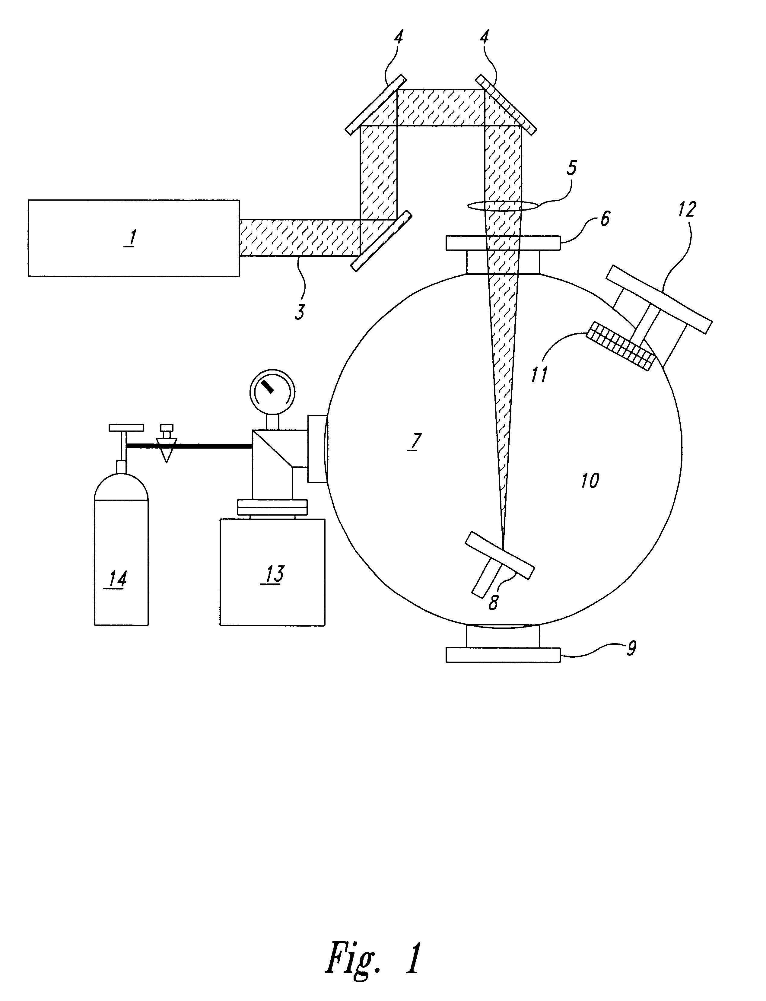
Method of deposition of thin films of amorphous and crystalline microstructures based on ultrafast pulsed laser deposition
a technology of ultra-fast pulsed laser and crystalline microstructure, which is applied in the direction of nuclear engineering, transportation and packaging, railway signalling, etc., can solve the problems of particulate problem severely restricting the commercial application of the existing pulsed laser deposition technique, and the widespread use of pulsed laser deposition as a thin film production method has not been widely used
- Summary
- Abstract
- Description
- Claims
- Application Information
AI Technical Summary
Benefits of technology
Problems solved by technology
Method used
Image

Examples
example 1
The Number of Evaporated Atoms
This example compares an estimate of the number of evaporated atoms or molecules per laser pulse for three different lasers with various repetition rates. To provide a meaningful comparison the optimal regime for carbon evaporation for each laser is considered for evaporation that takes place in vacuum. The vapour temperature along with the evaporation rate is proportional to the product I.sub.a.multidot.(t.sub.p).sup.1 / 2 and remains constant in the optimal evaporation regime. The maximum number of the evaporated atoms per single pulse
N.sub.evap =E.sub.p / .epsilon..sub.b =I.sub.a S.sub.foc t.sub.p / .epsilon..sub.b
1) conventional low repetition rate, high power laser: repetition rate R.sub.rep =25 Hz; t.sub.p =10 ns; pulse energy 0.05 J; absorbed laser intensity I.sub.a.about.2.multidot.10.sup.9 W / cm.sup.2 ; S.sub.foc.about.1 cm.sup.2. The number of evaporated atoms is .about.10.sup.17 atoms / pulse;
2) high repetition rate laser, long pulse: R.sub.rep =10 ...
example 2
Film Surface Study with Optical Microscopy, Scanning Electron Microscopy, and Atomic Force Microscopy
Optical microscope images of the thin carbon films deposited on a polished Si-wafer as a substrate using a 10 kHz, 120 ns laser, and a 60 ps, 76 MHz laser are shown in FIG. 3(b) and 3(c). For comparison, FIG. 3(a) shows an image of a substrate surface with a carbon film evaporated using the conventional method with a 10 ns 30 Hz powerful Nd:YAG laser. All the substrates were positioned at a distance of 20 mm from the target and the evaporation time was 10 mins in all experiments.
The images reveal strikingly different results on the particulate density on the substrate. The film deposited with the 30 Hz laser was covered with both spherical droplets and irregular particles in the micron size range with the particle density above 1,000 mm.sup.-2. This is quite typical for conventional evaporation with powerful lasers. The ejection of such hot particles during the evaporation process wa...
example 3
The monitored deposition rate on a substrate located R.sub.0 =150 mm from the target was in the range 2-6 .ANG. / s for the 10 kHz laser, and 0.8-2.5 .ANG. / s for the 76 MHz laser. To compare the rates to that for conventional deposition with low repetition rate powerful lasers it was assumed for the sake of simplicity the inverse square law for R.sub.0. The carbon film deposition rate extracted from [1] for R.sub.0 =3 cm was 2 .ANG. / s whilst higher rate of 3.5-5.5 .ANG. / s was measured in [2] for R.sub.0 =3.5 cm. The deposition rates achieved in the experiments for 10 kHz laser evaporation are .about.25 times higher than that in conventional laser deposition, and the deposition rate achieved with 76 MHz laser is 3-10 times higher. The potential exists to increase the deposition rate in ultrafast deposition technique up to 1000 times compared to that with conventional pulsed laser deposition method.
PUM
| Property | Measurement | Unit |
|---|---|---|
| Pressure | aaaaa | aaaaa |
| Pressure | aaaaa | aaaaa |
| Diameter | aaaaa | aaaaa |
Abstract
Description
Claims
Application Information