Resonator element, resonator, electronic device, and electronic apparatus

a resonator and element technology, applied in the direction of piezoelectric/electrostrictive/magnetostrictive devices, piezoelectric/electrostriction/magnetostriction machines, impedence networks, etc., can solve the problems of reducing the forming area of the electrode, the driving frequency cannot be satisfactorily lowered, and the torsional rigidity of each resonating arm is relatively high, and achieves high efficiency

Inactive Publication Date: 2013-02-12
SEIKO EPSON CORP
View PDF12 Cites 6 Cited by
  • Summary
  • Abstract
  • Description
  • Claims
  • Application Information

AI Technical Summary

Benefits of technology

[0010]According to this configuration, it is possible to excite the torsional vibration using the stretch vibration. Accordingly, it is possible to efficiently excite the torsional vibration. As a result, it is possible to lower a driving voltage of a resonator employing the resonator element.
[0040]Accordingly, it is possible to provide an electronic apparatus which can accomplish the decrease in size and frequency and vibrate in a torsional mode with high efficiency.

Problems solved by technology

However, in the crystal resonator described in JP-A-4-348606, since the section in the width direction of each resonating arm is rectangular as described above, the torsional rigidity of each resonating arm is relatively high and the driving frequency cannot be satisfactorily lowered.
When the resonating arm is narrowed to lower the torsional rigidity, the forming area of the electrodes is reduced, thereby not efficiently exciting the torsional vibration.

Method used


Image

  • Resonator element, resonator, electronic device, and electronic apparatus
  • Resonator element, resonator, electronic device, and electronic apparatus
  • Resonator element, resonator, electronic device, and electronic apparatus

Examples


first embodiment

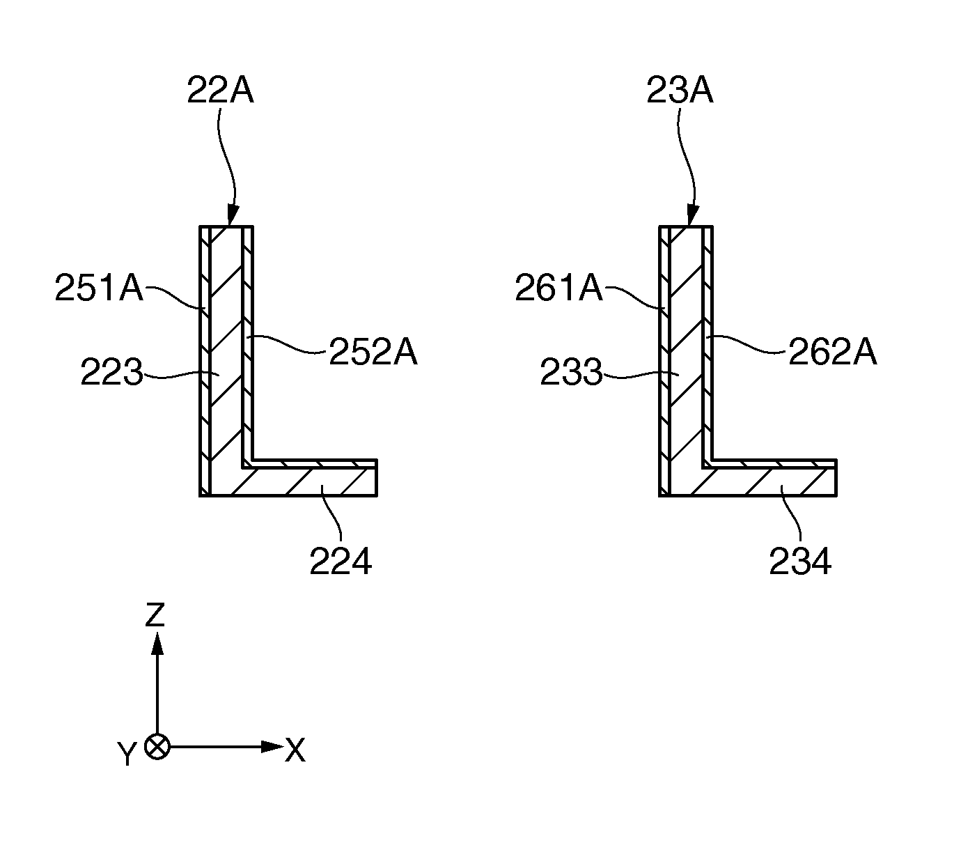
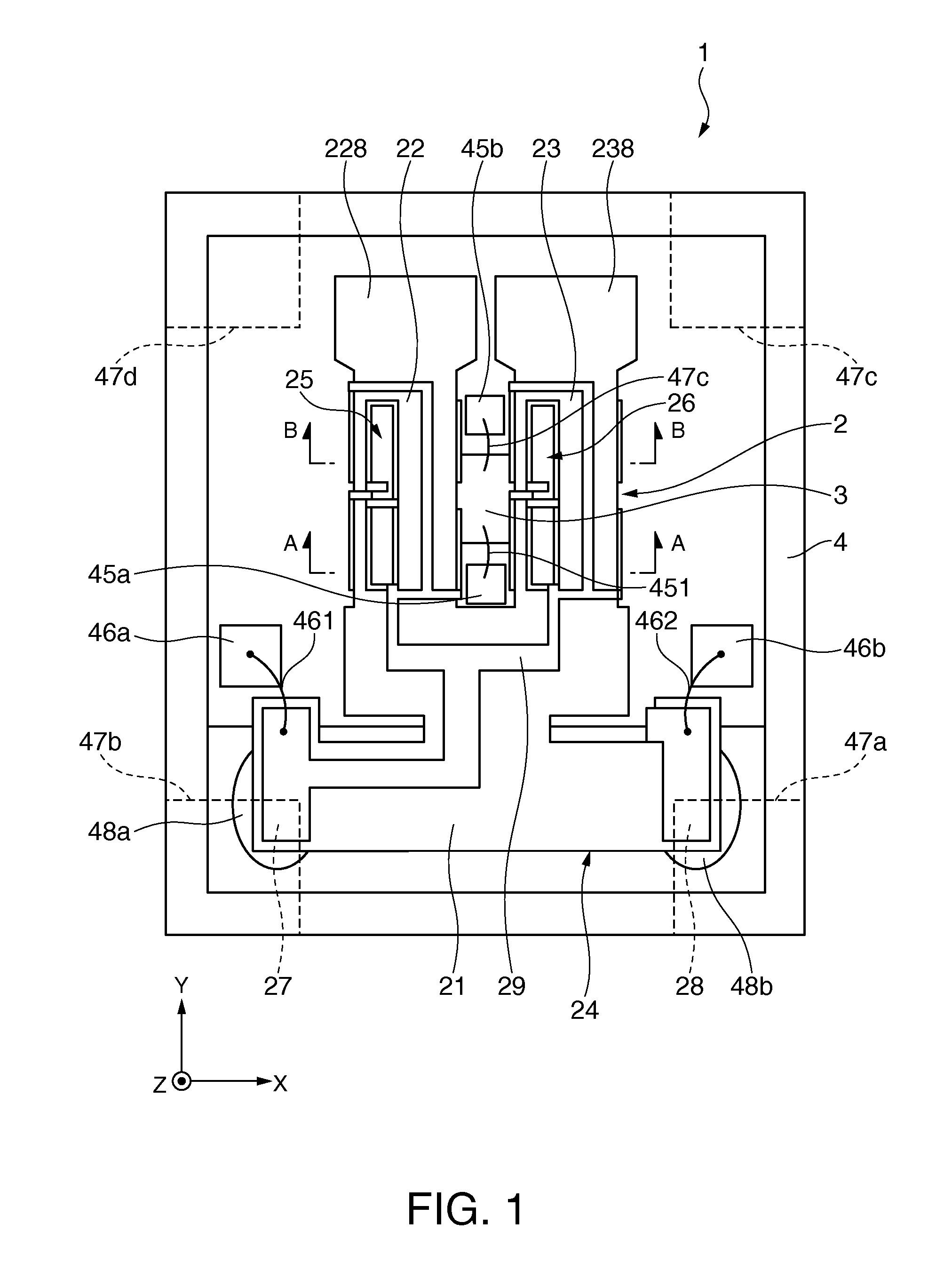
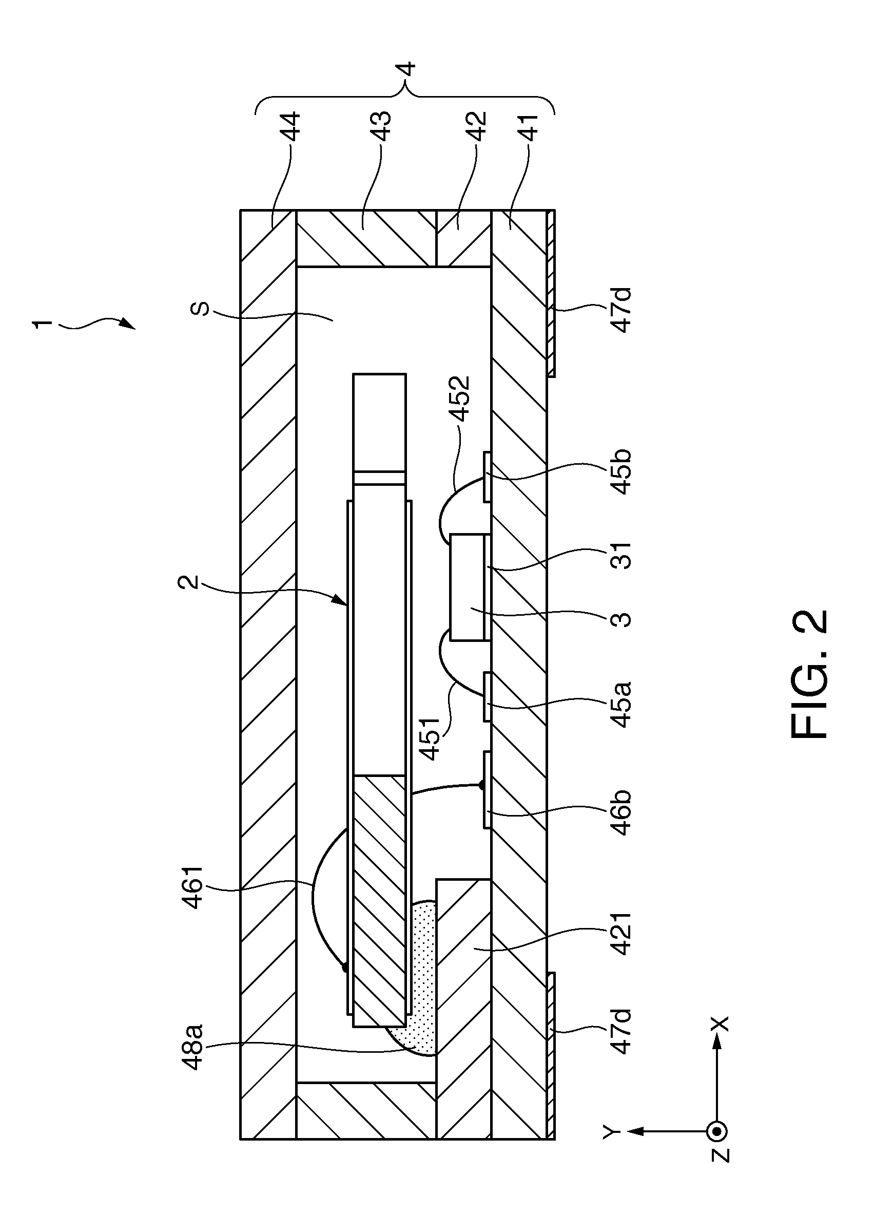
[0063]FIG. 1 is a top view of an electronic device according to a first embodiment of the invention. FIG. 2 is a sectional view of the electronic device shown in FIG. 1. FIG. 3 is a top view of a resonator element included in the electronic device shown in FIG. 1 (where electrodes are not shown). FIG. 4 is a bottom view of the resonator element included in the electronic device shown in FIG. 1. FIGS. 5A and 5B are sectional views of the resonator element included in the electronic device shown in FIG. 1, where FIG. 5A is a sectional view taken along line A-A of FIG. 1 and FIG. 5B is a sectional view taken along line B-B of FIG. 1. FIG. 6 is a partially-enlarged perspective view illustrating the behavior of a resonating arm of the resonator element shown in FIGS. 5A and 5B. In the drawings, an X axis, a Y axis, and a Z axis are shown as three axes perpendicular to each other. In the following description, the direction parallel to the X axis is defined as an “X axis direction”, the d...

second embodiment

[0146]An electronic device according to a second embodiment of the invention will be described below.

[0147]FIG. 7 is a top view illustrating a resonator element included in an electronic device according to the second embodiment of the invention. FIG. 8 is a sectional view (a sectional view along the width direction of the resonating arm) of the resonator element shown in FIG. 7.

[0148]Hereinafter, differences of an electronic device according to the second embodiment from the above-mentioned embodiment will be mainly described and the same configurations will not be described.

[0149]The electronic device according to the second embodiment is substantially the same as the first embodiment, except the sectional shape in the width direction of the resonating arm and the arrangement of the excitation electrodes. In FIGS. 7 and 8, the same elements as the above-mentioned embodiment are referenced by the same reference numerals. In FIG. 7, the interconnections and the connection electrodes...

third embodiment

[0162]An electronic device according to a third embodiment of the invention will be described below.

[0163]FIG. 9 is a top view illustrating a resonator element included in an electronic device according to the third embodiment of the invention. FIG. 10 is a sectional view (a sectional view along the width direction of the resonating arm) of the resonator element shown in FIG. 9.

[0164]Hereinafter, differences of an electronic device according to the third embodiment from the above-mentioned embodiment will be mainly described and the same configurations will not be described.

[0165]The electronic device according to the third embodiment is substantially the same as the first embodiment, except the sectional shape in the width direction of the resonating arm and the arrangement of the excitation electrodes. The electronic device according to the third embodiment is substantially the same as the second embodiment, except the posture in the section along the width direction of one resona...


PUM


Abstract

A resonator element includes at least one resonating arm that vibrates in a torsional mode, wherein the resonating arm includes a structural portion having a first portion disposed in a first direction in a sectional view in the width direction and a second portion connected to the first portion so that the center of gravity departs from the center of gravity of the first portion in the first direction and a second direction perpendicular to the first direction, wherein the first portion vibrates in a stretch mode in the length direction of the resonating arm with an application of a voltage, and wherein the second portion does not substantially vibrate in the stretch mode in the length direction of the resonating arm with the application of the voltage or vibrates in a stretch mode with a phase different from that of the first portion.

Description

BACKGROUND[0001]1. Technical Field[0002]The present invention relates to a resonator element, a resonator, an electronic device, and an electronic apparatus.[0003]2. Related Art[0004]Electronic devices such as crystal oscillators mounted on electronic apparatuses include a resonator such as a crystal resonator. A resonator having a tuning-fork resonator element including two resonating arms extending to be parallel to each other is known (for example, JP-A-4-348606).[0005]For example, in the crystal resonator described in JP-A-4-348606, two pairs of electrodes are disposed on a pair of surfaces facing each other in the width direction of each resonating arm having a rectangular section in the width direction. Among two pairs of electrodes, by applying voltages with inversed polarities to one pair of electrodes facing each other and the other pair of electrodes facing each other, each resonating arm can be made to vibrate in a torsional mode.[0006]By using this torsional vibration, i...

Claims


Application Information

Patent Timeline
Patent Type & Authority Patents(United States)
IPC IPC(8): H01L41/08
CPCH03H9/02062H03H9/0547H03H9/1021H03H9/21
Inventor YAMADA, AKINORI
Owner SEIKO EPSON CORP
Why Eureka
Try Eureka