Acoustic wave filter device

Active Publication Date: 2018-08-09
MURATA MFG CO LTD
View PDF1 Cites 0 Cited by
  • Summary
  • Abstract
  • Description
  • Claims
  • Application Information

AI Technical Summary

Benefits of technology

[0014]In an acoustic wave filter device according to a preferred embodiment of the present invention, the piezoelectric substrate has Euler Angles (0°±within range of about 5°, θ, 0°±within range of about 10°), 0 being in a range of not smaller than about 20° and not larger than about 50°. In this case, the Rayleigh wave is able to be efficiently excited.
[0015]In an acoustic wave filter de

Problems solved by technology

Meanwhile, in a bandpass filter including acoustic wave resonators, because the plurality of acoustic wave resonators are employed, even when the SH wave spurious appearing between the resonant

Method used


Image

  • Acoustic wave filter device
  • Acoustic wave filter device
  • Acoustic wave filter device

Examples


Embodiment Construction

[0034]The present invention will be clarified from the following description of examples of preferred embodiments of the present invention with reference to the drawings.

[0035]It is to be noted that the preferred embodiments described herein are merely illustrative, and individual elements may be partially replaced or combined with each other between the different preferred embodiments.

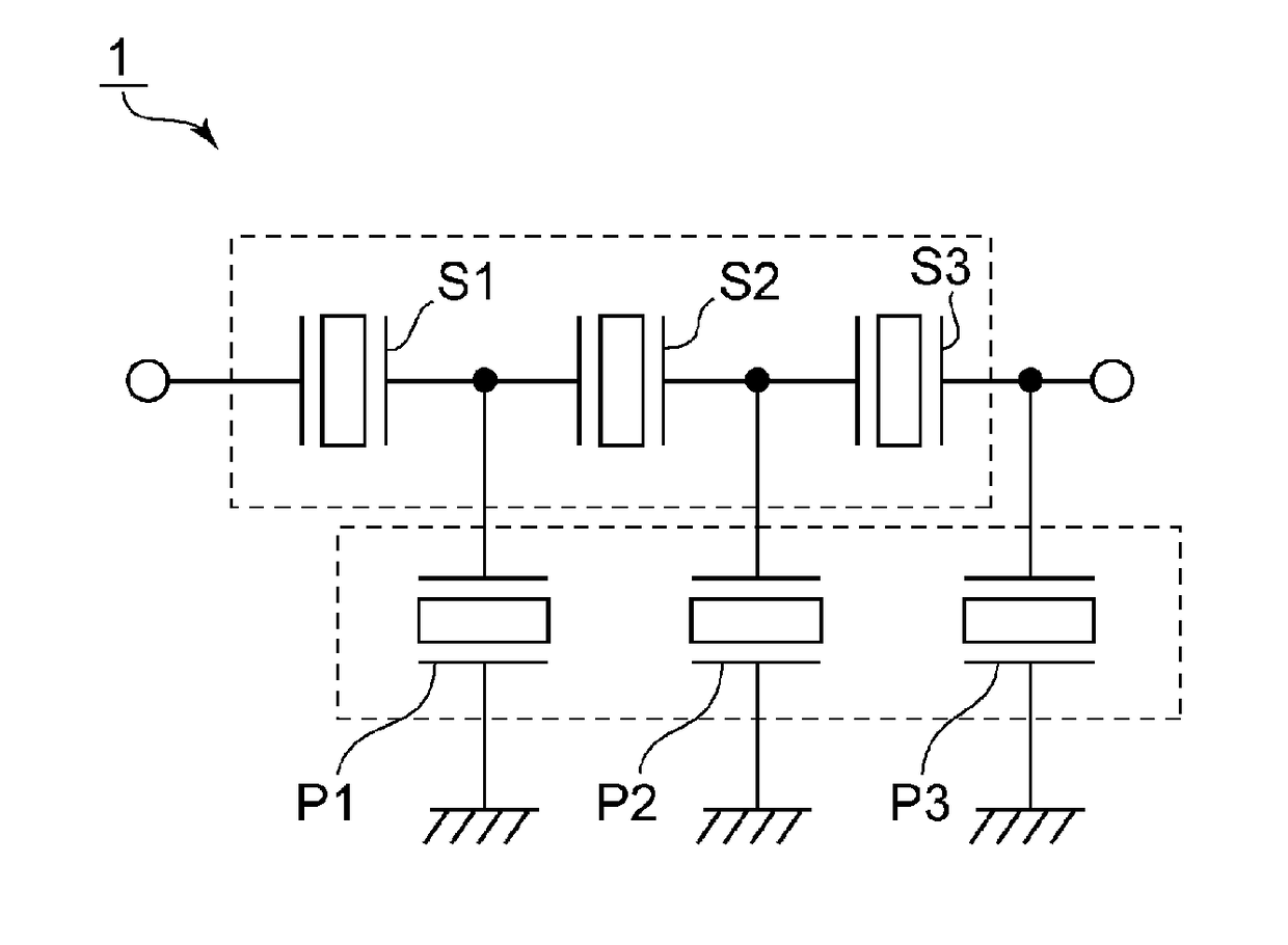
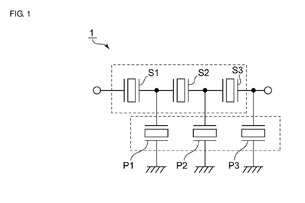
[0036]FIG. 1 is a circuit diagram of a ladder filter as an acoustic wave filter device according to one preferred embodiment of the present invention.

[0037]The acoustic wave filter device 1 includes a serial arm interconnecting an input terminal and an output terminal. In the serial arm, serial arm resonators S1 to S3 are successively connected in series.

[0038]A parallel arm resonator P1 is disposed in a parallel arm interconnecting a junction point between the serial arm resonators S1 and S2 and a ground potential. A parallel arm resonator P2 is disposed in a parallel arm interconnecting a junction p...


PUM


Abstract

A bandpass acoustic wave filter device includes an IDT electrode and a dielectric film disposed on a piezoelectric substrate including a LiNbO3 layer, and an acoustic wave resonator is defined by the IDT electrode. The acoustic wave resonator utilizes the Rayleigh wave, and a response of an SH wave excited by the acoustic wave resonator is outside a pass band of the acoustic wave filter device.

Description

CROSS REFERENCE TO RELATED APPLICATIONS[0001]This application claims the benefit of priority to Japanese Patent Application No. 2015-208925 filed on Oct. 23, 2015 and is a Continuation Application of PCT Application No. PCT / JP2016 / 073418 filed on Aug. 9, 2016. The entire contents of each application are hereby incorporated herein by reference.BACKGROUND OF THE INVENTION1. Field of the Invention[0002]The present invention relates to a bandpass acoustic wave filter device, which utilizes a Rayleigh wave.2. Description of the Related Art[0003]WO2007 / 125733 discloses an acoustic wave resonator utilizing a Rayleigh wave. In the acoustic wave resonator disclosed in WO2007 / 125733, an IDT (interdigital transducer) electrode is provided on a LiNbO3 substrate. A SiO2 film is laminated on the LiNbO3 substrate and covers the IDT electrode. WO2007 / 125733 states that an SH wave spurious appearing between a resonant frequency and an anti-resonant frequency is able to be suppressed by adjusting Eul...

Claims


Application Information

Patent Timeline
IPC IPC(8): H03H9/64H03H9/02H03H9/145H03H9/25
CPCH03H9/6489H03H9/02559H03H9/02637H03H9/145H03H9/25H03H9/14541H03H9/6436H03H9/6483
Inventor MIMURA, MASAKAZU
Owner MURATA MFG CO LTD
Why Eureka
Try Eureka