
Endoscope light emitting device, endoscope using same, and fluorescence imaging method

a light-emitting device and endoscope technology, applied in the field of endoscope light-emitting device, endoscope using light-emitting device, fluorescence imaging method, can solve the problems that the laser element emitted near-infrared light has not been able to sufficiently excite the icg, and the icg has not been sometimes sufficiently excited by the near-infrared light emitted

Active Publication Date: 2022-07-26
PANASONIC INTELLECTUAL PROPERTY MANAGEMENT CO LTD
View PDF13 Cites 0 Cited by
  • Summary
  • Abstract
  • Description
  • Claims
  • Application Information

AI Technical Summary

Benefits of technology

The present invention aims to solve problems in the prior art by providing an endoscope light emitting device that can efficiently excite fluorescent drugs and produce high-output near-infrared light. This device can be used in an endoscope and a fluorescence imaging method. The technical effects of this invention include improved visualization of tissue abnormalities and reduced risk of complications during surgery.

Problems solved by technology

However, when such a laser element as in Patent Literature 2 is used as an excitation source of the ICG, there are two problems as below.
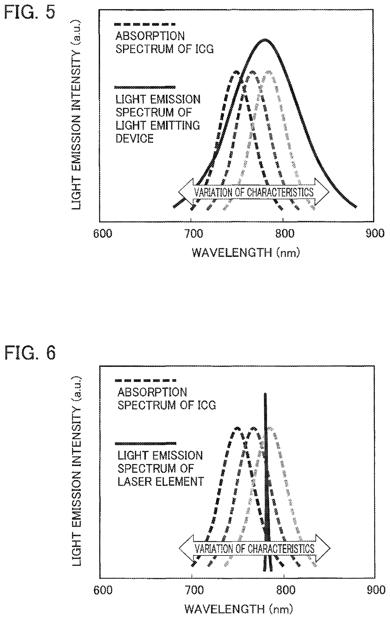
One of the problems is: since a full width at half maximum of a light emission spectrum of the near-infrared light emitted by the laser element is narrow, the ICG has not sometimes been sufficiently excited by the near-infrared light emitted by the laser element when excitation characteristics of the ICG change due to variation of characteristics.
The other problem is: the laser element that emits the near-infrared light has not been able to sufficiently excite the ICG since an output thereof in the wavelength range in which it is easy to excite the ICG is low.

Method used


Image

  • Endoscope light emitting device, endoscope using same, and fluorescence imaging method
  • Endoscope light emitting device, endoscope using same, and fluorescence imaging method
  • Endoscope light emitting device, endoscope using same, and fluorescence imaging method

Examples


example 1

[0106]An oxide phosphor for use in Example 1 was synthesized by using a preparation method using a solid phase reaction. The phosphor of Example 1 is an oxide phosphor represented by a composition formula of (Y0.98Ce0.02)3Mg2(AlO4)(SiO4)2. Note that the following compound powders were used as main raw materials at the time of synthesizing the oxide phosphor.

[0107]Yttrium oxide (Y2O3): purity 3N, Shin-Etsu Chemical Co., Ltd.

[0108]Cerium oxide (CeO2): purity 4N, Shin-Etsu Chemical Co., Ltd.

[0109]Aluminum oxide (θ-Al2O3): purity>4N5, Sumitomo Chemical Co., Ltd.

[0110]Magnesium oxide (MgO): purity 4N, Kojundo Chemical Laboratory Co., Ltd.

[0111]Silicon dioxide (SiO2): purity>3N, Nippon Aerosil Co., Ltd.

[0112]Note that, for the purpose of improving reactivity between the raw materials, AKP-G008 made by Sumitomo Chemicals Co., Ltd. was used as aluminum oxide. Moreover, in the Example, the following compound powders were used as reaction accelerators.

[0113]Aluminum fluoride (AlF3): purity 3N...

example 2 , example 3

Example 2, Example 3

[0117]Nitride phosphors for use in Example 2 and Example 3 were synthesized by using a preparation method using a solid phase reaction. The phosphor of Example 2 is a nitride phosphor represented by a composition formula of La2.991Ce0.009(Si,A)6(N,O)11-x. Moreover, the phosphor of Example 3 is a nitride phosphor represented by a composition formula of La2.982Ce0.012(Si,A)6(N,O)11-x.

[0118]At the time of synthesizing the nitride phosphor, lanthanum nitride (III) (LaN), silicon nitride powder (Si3N4), aluminum nitride powder (AlN), and cerium fluoride powder (CeF3) were used as main raw materials.

[0119]First, the above-described raw materials were weighed so as to form a compound with a stoichiometric composition, which is La2.991Ce0.009(Si,Al)6(N,O)11-x, La2.982Ce0.012(Si,Al)6(N,O)11-x. However, the LaN powder was weighed to an amount larger by 24% than a stoichiometric value thereof.

[0120]Next, the weighed raw materials were dry-mixed with one another by using a m...

example 4

[0121]An oxide phosphor for use in Example 4 was synthesized by using a preparation method using a solid phase reaction. The phosphor of Example 4 is an oxide phosphor represented by a composition formula of (Ca0.1Sr0.897Eu0.003)Sc2O4. Note that, the following compound powders were used as main raw materials at the time of synthesizing the oxide phosphor.

[0122]Calcium carbonate (CaCO3): purity 3N, Wako Pure Chemical Industries, Ltd.

[0123]Strontium carbonate (SrCO3): purity 3N, Wako Pure Chemical Industries, Ltd.

[0124]Scandium oxide (Sc2O3): purity 3N, Shin-Etsu Chemical Co., Ltd.

[0125]Europium oxide (Eu2O3): purity 3N, Shin-Etsu Chemical Co, Ltd.

[0126]First, the above-described raw materials were weighed so as to obtain a compound with a stoichiometric composition, which is (Ca0.1Sr0.897Eu0.003)Sc2O4. Next, the weighed raw materials were put into a beaker into which pure water was poured, and were stirred for 1 hour by using a magnetic stirrer. Thus, a slurry-like mixed raw material...


PUM


Abstract

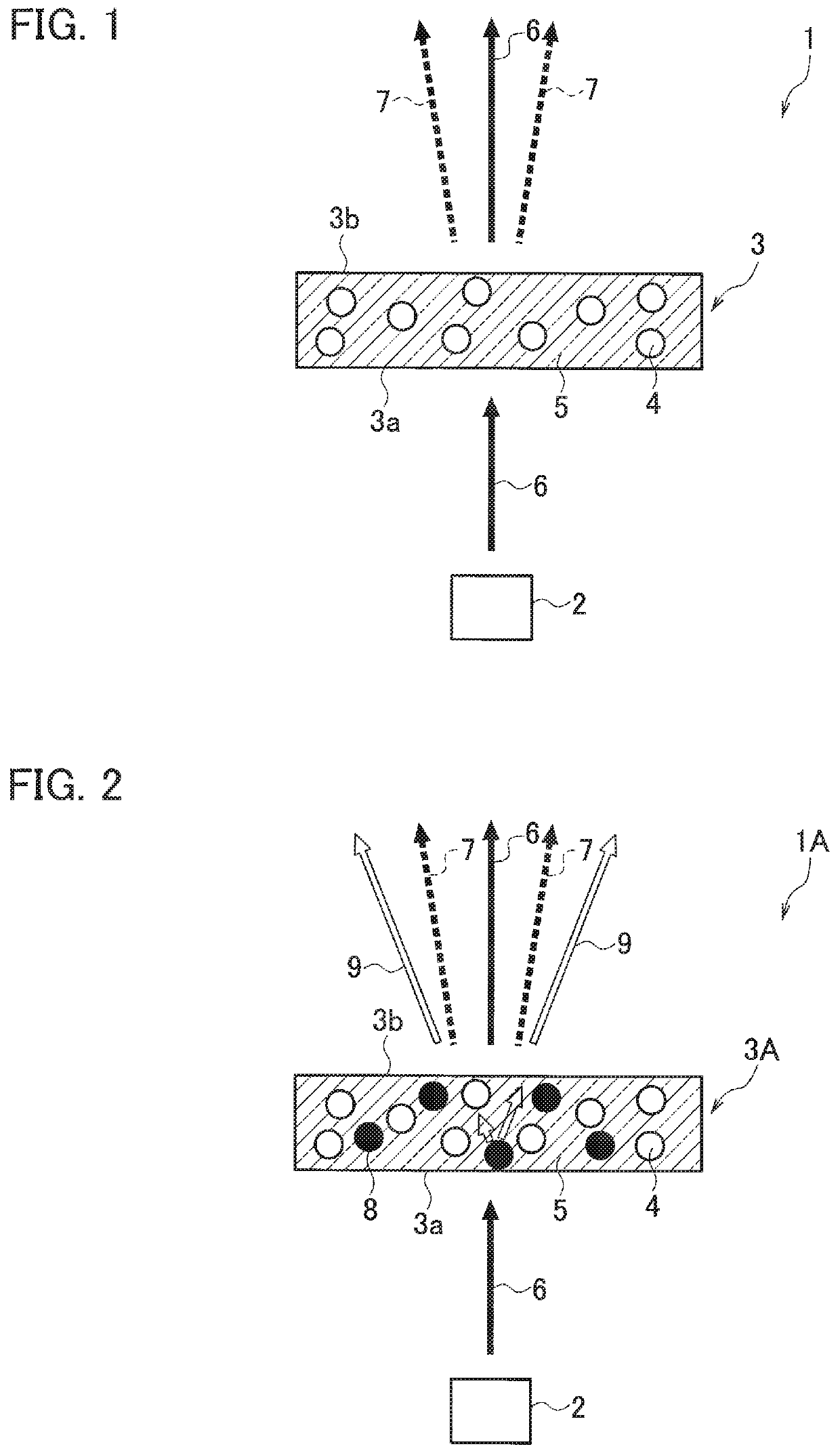
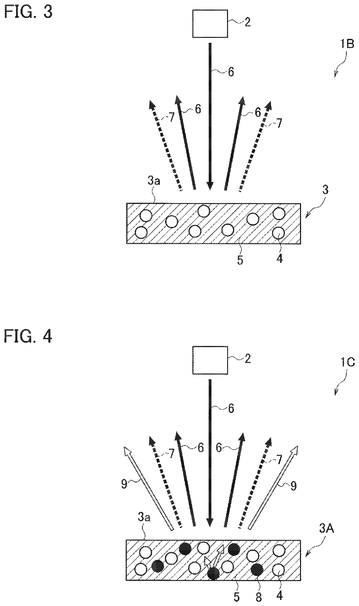
An endoscope light emitting device (1) is a light emitting device for use in a fluorescence imaging method. The endoscope light emitting device includes: a solid-state light emitting element (2); and a wavelength converter (3) including a first phosphor (4) that emits first wavelength-converted light (7), wherein the first wavelength-converted light has a light component across at least a whole of a wavelength range of 700 nm or more and 800 nm or less. An endoscope (11) includes the endoscope light emitting device. A fluorescence imaging method is a method using the endoscope light emitting device or the endoscope, and includes the steps of: administering a fluorescent drug to a subject; and applying the first wavelength-converted light (7) to the subject with whom the fluorescent drug has made contact.

Description

TECHNICAL FIELD[0001]The present invention relates to an endoscope light emitting device, an endoscope using the light emitting device, and a fluorescence imaging method.BACKGROUND ART[0002]Heretofore, there has been known a method of inspecting whether or not a tumor is present in a biological tissue by using optical characteristics of the biological tissue, for Example, absorption, scattering, and the like. In Patent Literature 1, there is disclosed a biological tissue inspection device including: a light source that irradiates an inspection area of a biological tissue and emits incoherent light; and a light detector that detects reflected light or transmitted light. In general, such an inspection device is called an optical coherence tomography device, and such a method is called an optical coherence tomography method.[0003]Meanwhile, as such a technique of inspecting whether or not a tumor is present in a biological tissue and identifying a position of the tumor, a technique cal...

Claims


Application Information

Patent Timeline
IPC IPC(8): A61B1/00A61B1/06A61B1/04A61B1/07G02B23/24
CPCA61B1/0684A61B1/043A61B1/0653A61B1/07G02B23/2461G02B23/2469G02B5/208
Inventor ABE, TAKESHIOSHIO, SHOZO
Owner PANASONIC INTELLECTUAL PROPERTY MANAGEMENT CO LTD
Learn More