Energy storage device

a technology of energy storage and energy storage, applied in the field of flywheels, can solve the problems of increasing manufacturing and operation costs, potential failure points, and proposed solutions that are not designed primarily for efficient energy storage or conversion, and achieves the effects of ensuring overall stability of the device, large changes in stored energy, and low strain on the sha

Inactive Publication Date: 2013-02-12
ACHIRILOAIE IOAN +1
View PDF30 Cites 11 Cited by
  • Summary
  • Abstract
  • Description
  • Claims
  • Application Information

AI Technical Summary

Benefits of technology

[0010]Attachment of the masses to the shaft is accomplished via synchronized adjustable linking elements. These elements urge movement of the masses synchronously during operation, ensuring overall stability of the device and low strain on the shaft. For example, the synchronized adjustable linking elements may be made up of a bushing, a disk, and several arms and levers. The bushing is slidingly attached to the shaft allowing sliding as necessary during operation, the sliding being coupled with movement of the masses relative to the shaft. The disk is attached to the shaft at a fixed position. Each arm is pivotally attached to the disk with a first end, and attached to one mass with a second end. Each lever has one end jointly attached to the bushing and the other end jointly attached to one arm. Thus, changes to shaft angular velocity cause changes of centrifugal forces, and the synchronized adjustable linking elements allow synchronized movement of the masses relatively to the shaft to be effected solely under the influence of the centrifugal forces.
[0011]The energy storage device can also have one or more elastic elements that are positioned to oppose movement of the masses with increased angular velocity of the shaft at least over a part of the motion path of the masses. For example, elastic elements may be of compression type and positioned such that they compress when the angular velocity of the shaft increases. In some embodiments, the elastic element or elements are pretensioned. An elastic element may be positioned between the bushing and the disk in a device of a configuration as described above, opposing movement of the bushing towards the disk. Alternatively or additionally, elastic elements may be positioned between the disk and the masses, opposing movement of the masses towards the disk. The elastic elements store some of the energy applied to the shaft in the form of potential elastic energy, and allow for large changes in the stored energy with relatively little change of the angular velocity of the shaft. Thus, changes of total energy content of the device causes motion of the masses coupled with minimal changes to shaft angular velocity.
[0013]The energy storage devices have various applications where storage and retrieval of kinetic energy is desirable. For example, they may be used for wind farms to store kinetic energy from wind mills and retrieve it when necessary. They may also be used for the propulsion of vehicles. Other applications include hydroelectric and solar power storage and uninterrupted power supplies (UPS) where flywheel based energy storage is more desirable than battery-based UPS for short power disruption.

Problems solved by technology

These characteristics are undesirable for certain applications partly because of they require output power conditioning.
This complexity introduces multiple potential points of failure and increases manufacturing and operation costs.
Some of the proposed solutions are not designed primarily for efficient energy storage or conversion.
Besides, flywheels operate at high velocities, imposing strict safety and durability constrains on the materials, and making implementation of some of the complex designs described in the literature even more challenging.

Method used


Image

  • Energy storage device
  • Energy storage device
  • Energy storage device

Examples


Embodiment Construction

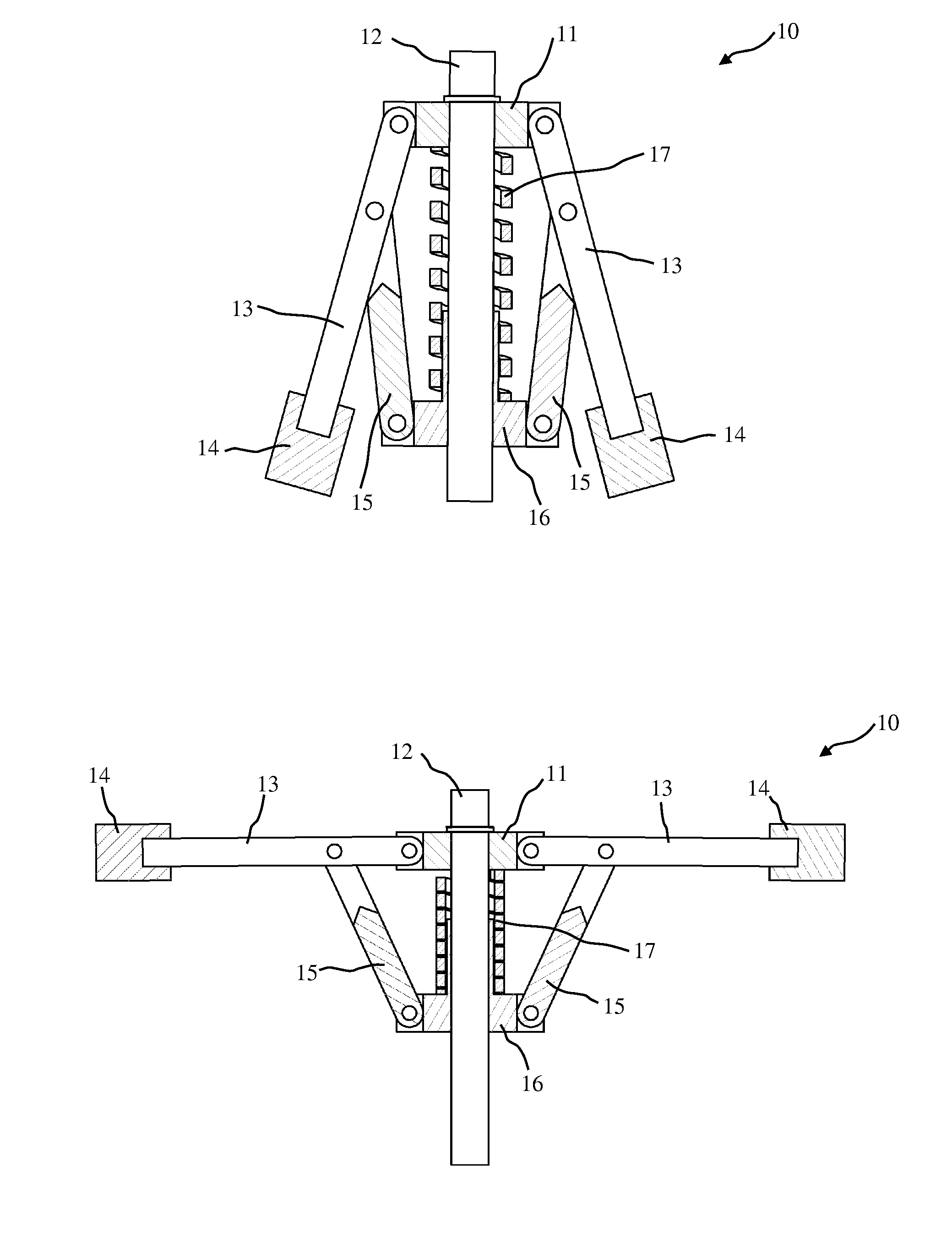
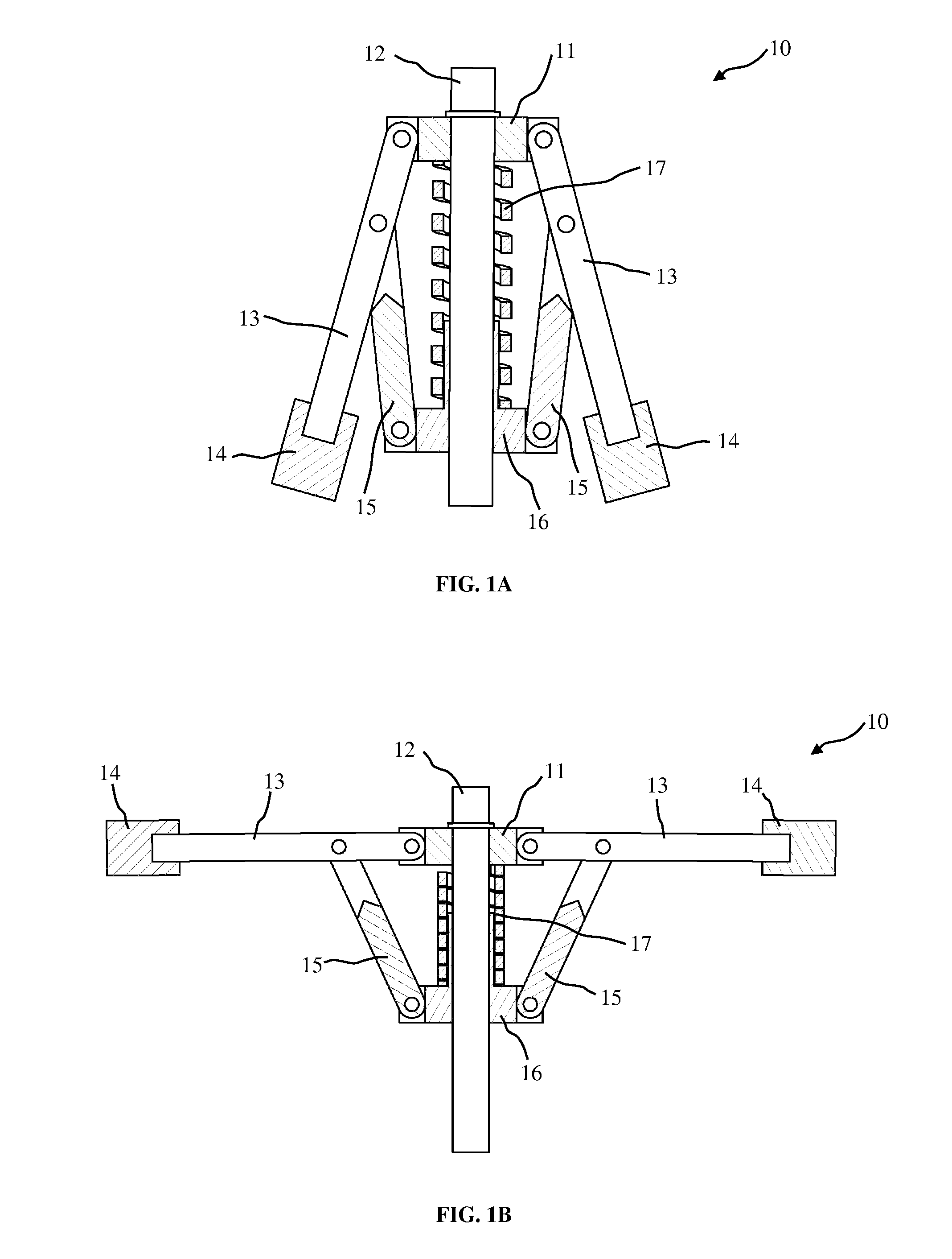
[0027]The subject invention relates to a device that varies its moment of inertia without any external means and, at the same time, controls the shaft angular velocity. Any additional energy input to the device is stored as both rotational kinetic energy and potential elastic and gravitational energy by the synchronous motion of a plurality of masses. The potential energy is recovered when the masses are moved to positions corresponding to smaller moments of inertia. Through the selection of mass placement and elastic elements, the storage and release of energy from the energy storage device can be done with relatively small variations in shaft angular velocity.

[0028]The energy storage device comprises a disk mounted at a fixed position to a vertical shaft. In some embodiments, the disk is massive and of a significant radius, acting in operation essentially as a fixed moment of inertia flywheel. In other embodiments the disk may be a bushing serving to support the components of the ...


PUM

PropertyMeasurementUnit
centrifugal forcesaaaaaaaaaa
elastic forcesaaaaaaaaaa
total energy contentaaaaaaaaaa

Abstract

An energy storage device having a variable momentum of inertia uses centrifugal forces acting on movable masses to self adjust its moment of inertia. The adjustment of the moment of inertia occurs without any additional energy input. Energy is stored as rotational kinetic energy and potential elastic and / or gravitational energy.

Description

REFERENCE TO RELATED APPLICATIONS[0001]This application claims the benefit of U.S. Provisional Application Ser. No. 61 / 151,175, filed Feb. 9, 2009, the entire contents of which are incorporated herein by reference.FIELD OF INVENTION[0002]The invention relates to methods and devices for storage of energy, and more specifically to flywheels that store energy in both kinetic and potential energy form.BACKGROUND OF INVENTION[0003]Flywheels are employed to store energy as rotational kinetic energy when the production exceeds demand or in machines that require large amounts of energy for short periods of time. In case of the production of electrical energy from wind, for example, it is typical to have excess energy with respect to demand in high wind conditions. For wind farm applications, the excess energy can be stored in a flywheel as rotational kinetic energy and released as electrical energy (power) when the demand becomes larger than the energy (power) produced.[0004]To maximize the...

Claims


Application Information

Patent Timeline
Patent Type & Authority Patents(United States)
IPC IPC(8): H02K7/02
CPCF16F15/31Y10T29/49826Y10T74/2128Y02E60/16F03G3/08
Inventor ACHIRILOAIE, IOANANTOHE, BOGDAN V.
Owner ACHIRILOAIE IOAN
Why Eureka
Try Eureka