Coil

a coil and coil body technology, applied in the field of advantageous coils, can solve the problems of coil strength, surface of coil, winding wire coating damage, winding wire breakage, etc., and achieve the effect of convenient wounding

Active Publication Date: 2013-02-12
SUMIDA CORP
View PDF10 Cites 3 Cited by
  • Summary
  • Abstract
  • Description
  • Claims
  • Application Information

AI Technical Summary

Benefits of technology

[0010]The present invention has been created to resolve the above-described problems and it is an object thereof to provide a coil in which one of a first end of wire and a second end of wire is wound from an inner circumferential side towards an outer circumferential side, and the other one of the first end of the wire and the second end of the wire is drawn forth from the inner circumferential side to the outer circumferential side, wherein a significant increase in a winding height at crossing portions of the first end of the wire and the second end of the wire compared to a winding height in other portions is prevented and the coil can be easily manufactured.
[0011]The coil in accordance with the present invention has the following features that make it possible to attain the above-described object.
[0020]Further, when the plurality of wires are wound together, it has effect in a skin effect. Yet another advantage is that the coil can be easily wound, without using a winding apparatus of larger size, as in the case in which the a winding method is used.

Problems solved by technology

However, the problem related to the coil described in Japanese Patent Application Laid-open No. 2002-170729 is that because the first end of the wire and the second end of the wire are wound in the mutually opposite directions and the winding wires are piled up in two layers at the crossing portions thereof, a portion with a height twice the diameter of the wires appears along the crossing portions.
Further, when the coil is an air-core coil, problems are related to the coil strength because of the structure in which the winding wires are piled up in two layers.
In the case of the coil described in Japanese Patent Application Laid-open No. 2006-049750, since the flat surface of the wound coil is concaved along the draw-forth line of the winding start end side from the inner circumferential side towards the outer circumferential side, stresses are applied to the flat surface of the coil and the coating on the winding wire can be damaged or the winding wire can be broken.
Further, due to concavity on the flat surface of the wound coil, there may be a problem that the winding wire protrudes at other portions.

Method used


Image

  • Coil
  • Coil
  • Coil

Examples


Embodiment Construction

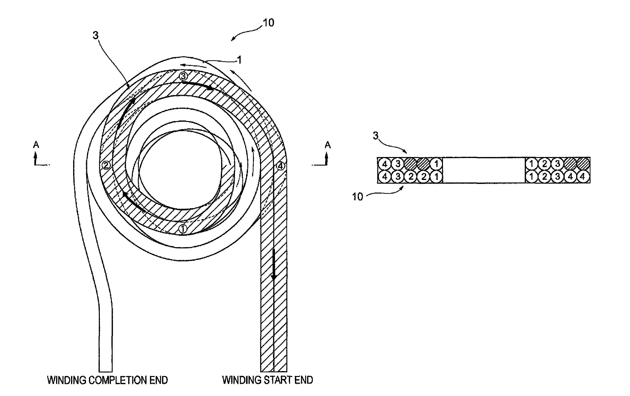
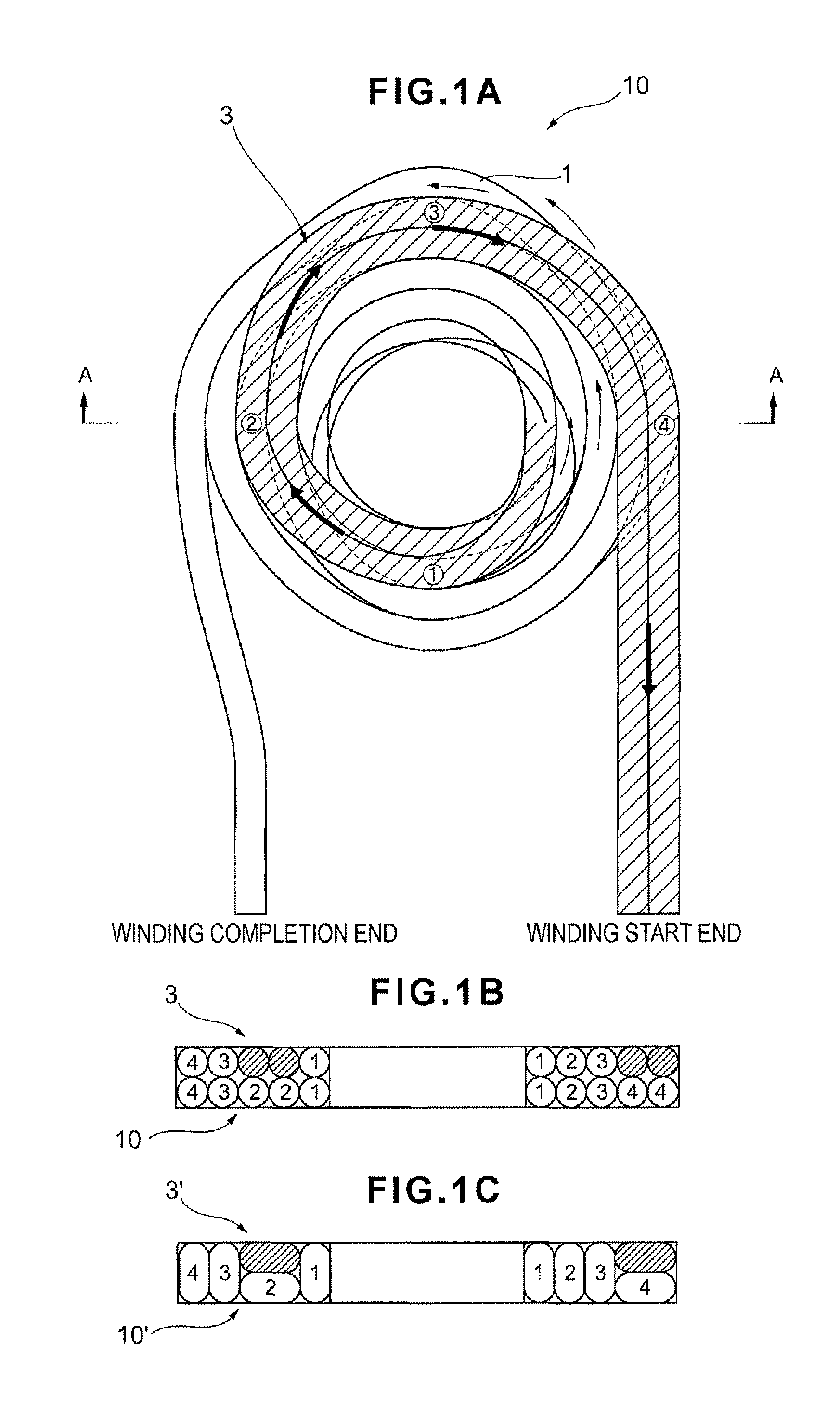
[0033]An embodiment of the coil in accordance with the present invention will be described below with reference to FIGS. 1 to 5 and FIG. 12.

[0034]FIG. 1 shows a coil 10 of the present embodiment, and a basic shape serving as a prototype thereof is shown in FIG. 12. FIG. 1 illustrates a case in which only four below-described crossing portions are provided for purpose of convenience of explanation. Further, the word “wire” is used in an explanation of the present invention. The “wire” means one line-shaped material provided with an insulated film on a surface of conductor which has conductivity such as copper, silver, etc.

[0035]Thus, a coil 10D shown in FIG. 12 is a flat air-core monolayer spirally wound coil (for example, disclosed in Japanese Patent Application Laid-open No. 2007-324532). In this coil, two winding wires having a diameter about half that of the winding wire that has been usually used are piled up vertically. At the winding completion end side, the two winding wires ...


PUM

PropertyMeasurementUnit
thicknessaaaaaaaaaa
total thicknessaaaaaaaaaa
contour shapeaaaaaaaaaa

Abstract

In the winding wire at the winding completion end side, two wires are piled up vertically and wound together from the inner circumferential side towards the outer circumferential side. The winding wire at the winding start end side that has remained on the inner circumferential side is drawn forth from the inner circumferential side to the outer circumferential side so as to form a curve along the flat surface of the coil. In the crossing portions of the winding wire at the winding completion end side and the winding wire at the winding start end side, the two wires of each winding wire are superimposed and caused to cross each other in a state in which the wires are laid down transversely.

Description

RELATED APPLICATIONS[0001]This application claims the priority of Japanese Patent Application No. 2009-239738 filed on Oct. 16, 2009 and No. 2010-182794 filed on Aug. 18, 2010, which are incorporated herein by reference.BACKGROUND OF THE INVENTION[0002]1. Field of the Invention[0003]The present invention relates to an advantageous coil as a thin-type coil for use in an electric device, and more particularly to a coil in which either of a first end of wire and a second end of wire is wound from an inner circumferential side towards an outer circumferential side, whereas the other end of wire is drawn forth from the inner circumferential side to the outer circumferential side.[0004]2. Description of the Prior Art[0005]An α winding method is generally known as a method for winding a coil by which a first end of wire and a second end of wire are both wound around from the inner circumferential side towards the outer circumferential side. With this winding method, as indicated in Japanes...

Claims


Application Information

Patent Timeline
Patent Type & Authority Patents(United States)
IPC IPC(8): H01F27/28H01F27/30
CPCH01F17/02H01F27/2823H01F41/0641H01F41/0625H01F27/2871H01F37/005H01F41/0629H01F41/0637H01F38/14H01F41/069H01F41/07H01F41/084H01F41/086
Inventor KIKUCHI, SHUICHIMEGURO, FUMIHITOHATAYAMA, YOSHIYUKI
Owner SUMIDA CORP
Why Eureka
Try Eureka