

Solid-state imaging device, driving method thereof, and imaging apparatus
a technology of solid-state imaging and driving method, which is applied in the direction of color television details, television system details, television systems, etc., can solve the problems of affecting the development of image quality, so as to achieve the effect of reducing the time difference between the long time exposure image and the short time exposure image and facilitating the generation of wide dynamic rang
- Summary
- Abstract
- Description
- Claims
- Application Information
AI Technical Summary
Benefits of technology
Problems solved by technology
Method used
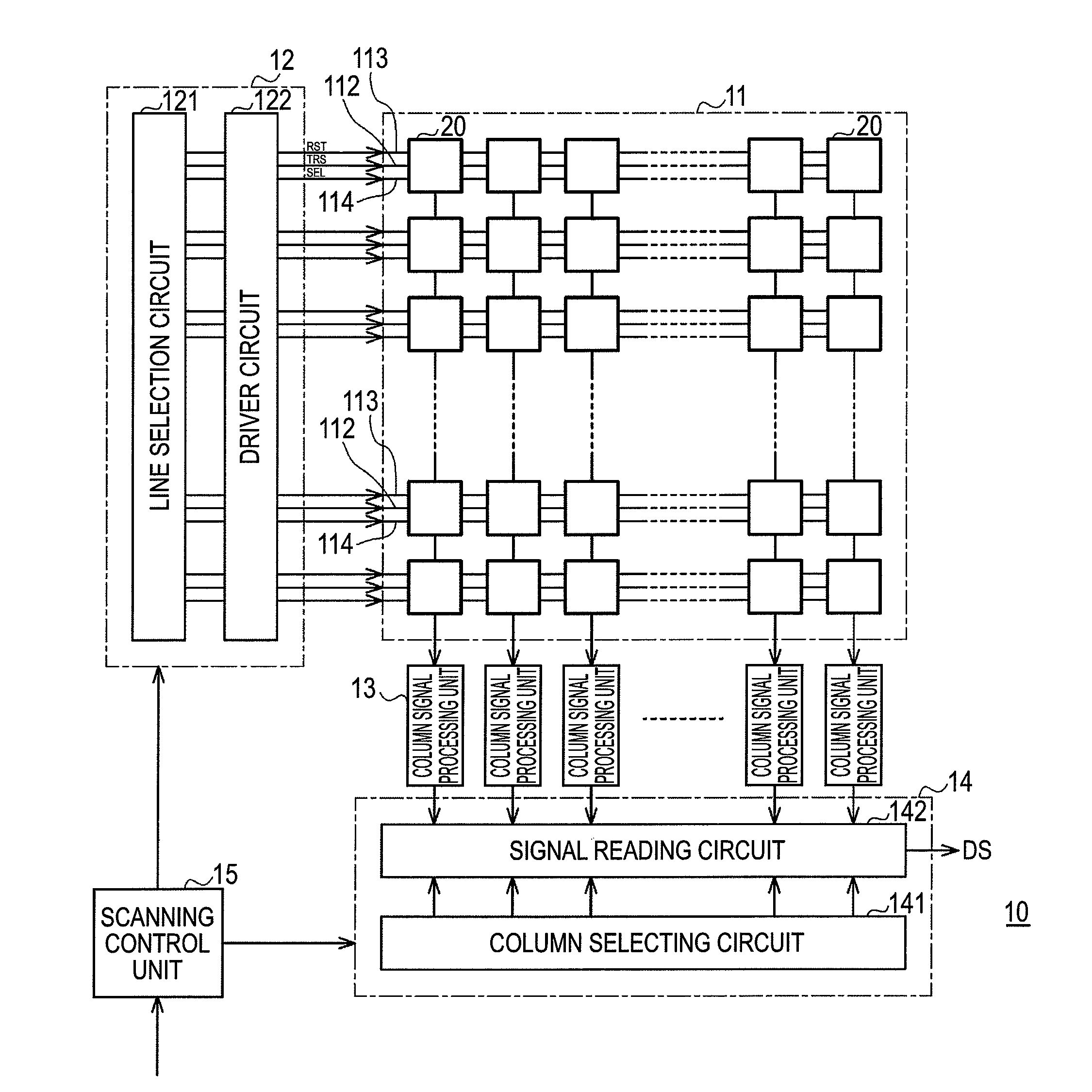
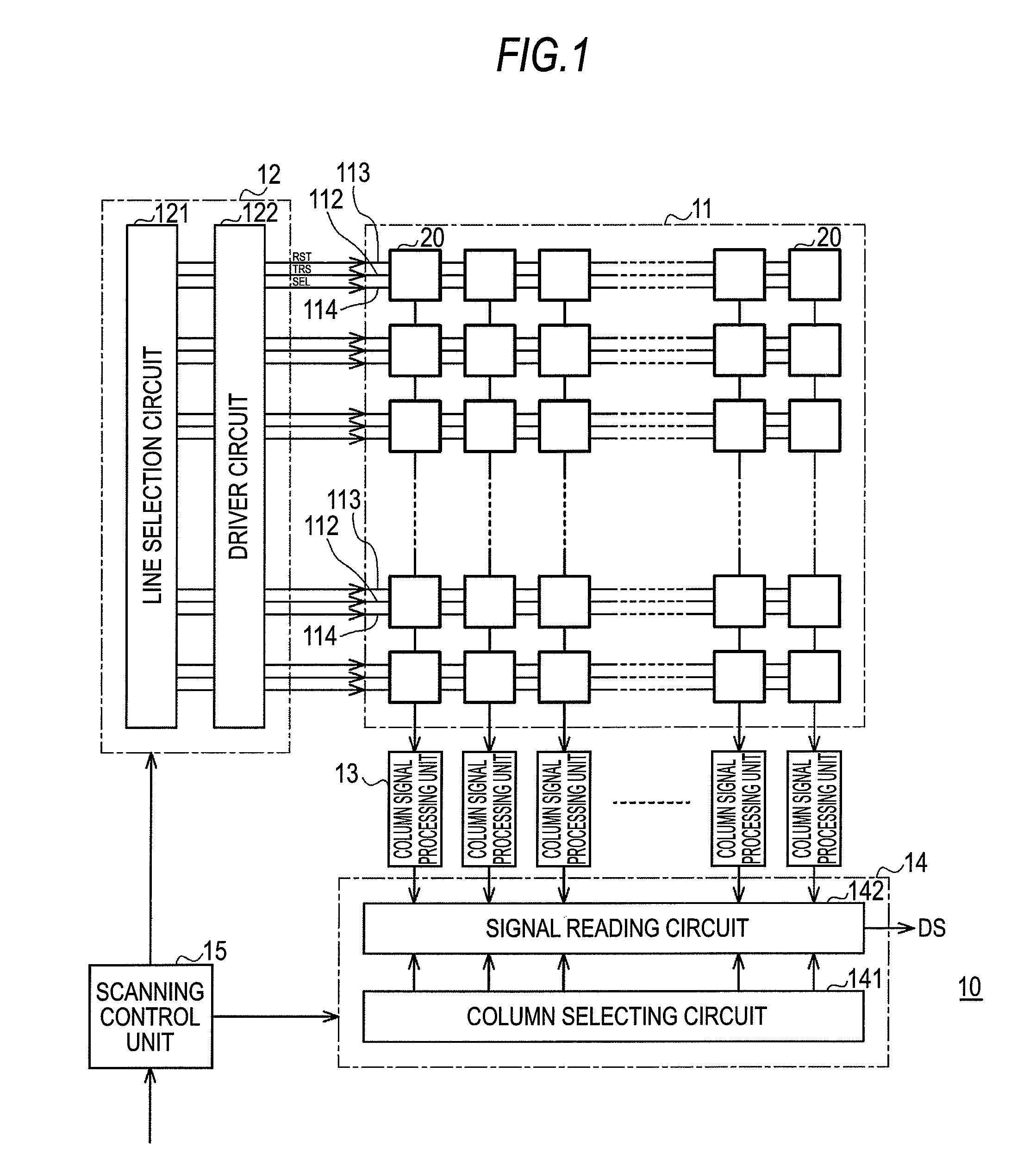
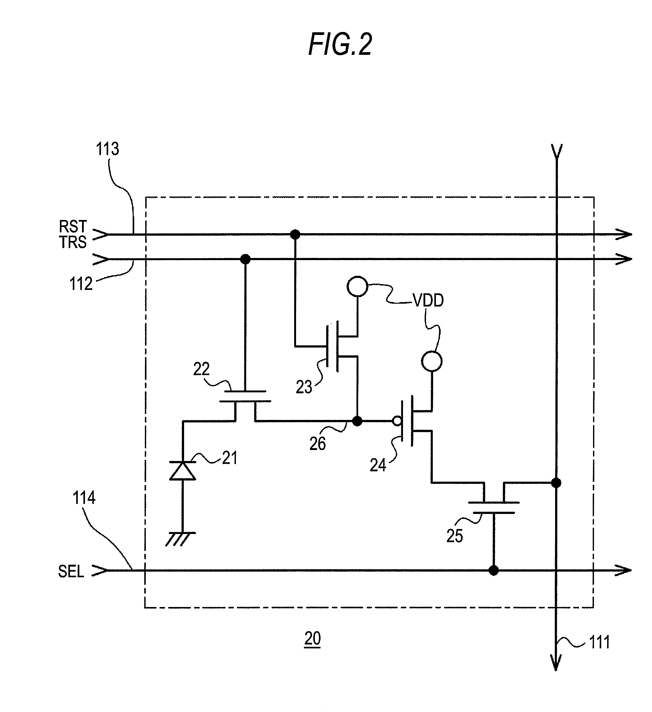
Image

Examples
first embodiment
Operation of First Embodiment
[0079]Next, the operation of the first embodiment will be described. In the reading of the signal electric charges, read-out of pixels corresponding to one line for which long time exposure has been completed and read-out of pixels corresponding to one line for which short-time exposure has been completed are alternately performed by allowing selection of one line shifted from the position of the scanning order to be included in the line selection for the scanning direction. In addition, a line positioned far away from the position of the scanning order in accordance with another exposure period is selected, and thereby a read-out operation of signal electric charges of the selected line also serves as a reset operation for starting exposure of another exposure period other than the exposure period of the read-out signal electric charges.
[0080]FIGS. 4A to 4G represent timings of each signal line for reading out signal electric charges. FIG. 4A represents...
second embodiment
Operation of Second Embodiment
[0104]Next, the operation of a second embodiment will be described. A scanning control unit 15 allows selection of a line shifted in accordance with each exposure period from the position of the scanning order to be included in the line selection performed in the scanning direction by a vertical scanning unit 12, and thereby sequentially outputting the image signal for each exposure period in the unit of one line from a horizontal scanning unit 14. The four exposure periods having different lengths are set to a long time exposure period Tl and three short time exposure periods of Ts1 to Ts3 in the order of the lengths of the exposure periods. For example, the lengths of the exposure periods are assumed to satisfy the conditions of “Tl>Ts3>Ts2>Ts1” and Tf=“Tl+Ts1+Ts2+Ts3”.
[0105]FIGS. 9A to 9F are diagrams illustrating the operation of the second embodiment. FIG. 9A shows a temporal change in the signal electric charges accumulated in a photo diode of a p...
third embodiment
Operation of Third Embodiment
[0125]Next, the operation of the third embodiment will be described. Similarly to the first and second embodiments, by allowing selection of a line shifted from the position of the scanning order to be included in the line selection for the scanning direction, read-out of pixels corresponding to one line for which the long time exposure has been completed and read-out of pixels corresponding to one line for which the short time exposure has been completed are alternately performed in the read-out of signal electric charges. In addition, the amount of shift is set in accordance with the exposure period, and the read-out operation of the signal electric charges also serves as a reset operation at the start of the next exposure.
[0126]FIGS. 11A to 11F are diagrams illustrating the operation of the third embodiment. FIG. 11A shows a temporal change in the signal electric charges accumulated in a photo diode of a pixel of line (n) for a low luminance portion a...
PUM
 Abstract
Description
Claims
Application Information