
Method and apparatus for transmit beamforming

a beamforming and transmitting technology, applied in the field of wireless communication systems, can solve the problems of antenna transceivers not using transmit beamforming, ieee 802.11b standard does not provide an interoperable protocol for channel training,

Active Publication Date: 2013-02-12
MARVELL ASIA PTE LTD
View PDF12 Cites 18 Cited by
  • Summary
  • Abstract
  • Description
  • Claims
  • Application Information

AI Technical Summary

Benefits of technology

This patent describes a method and apparatus for improving the reception of signals transmitted by multiple antennas. The technical effects of this patent include improved signal-to-noise ratios, improved signal quality, and better overall performance of the transmission system. This is achieved by using a rake receiver with multiple groups of rake fingers that correspond to different channels, and selecting one coefficient from each group to generate a transmit steering vector. This steering vector is then applied to signals to be transmitted, resulting in improved performance of the transmission system.

Problems solved by technology

But the IEEE 802.11b Standard does not provide an interoperable protocol for channel training for transmit beamforming.
As a result, many multiple antenna transceivers do not utilize transmit beamforming when transmitting according to the IEEE 802.11b Standard to a single antenna receiver.

Method used


Image

  • Method and apparatus for transmit beamforming
  • Method and apparatus for transmit beamforming
  • Method and apparatus for transmit beamforming

Examples


Embodiment Construction

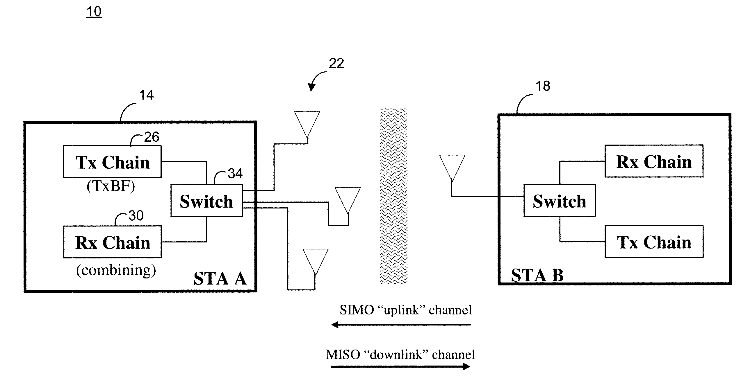
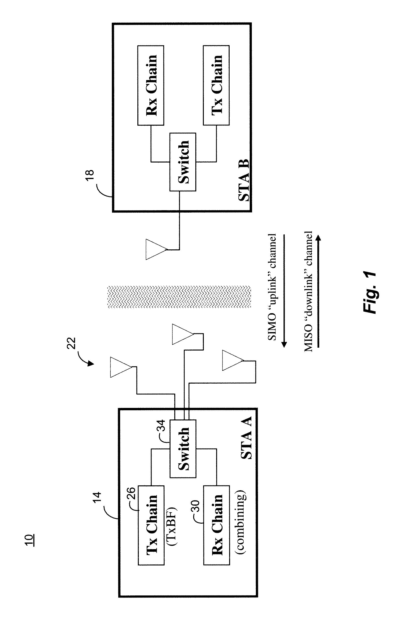
[0039]FIG. 1 is a block diagram of an example communication system 10 having a multiple antenna transceiver 14 and a single antenna transceiver 18. For example, the multiple antenna transceiver 14 may be a wireless local area network (WLAN) router, and the single antenna transceiver 18 may be a mobile unit. The channel from the single antenna transceiver 18 to the multiple antenna transceiver 14 may be referred to as a SIMO channel, and the channel from the multiple antenna transceiver 14 to the single antenna transceiver 18 may be referred to as MISO channel. Although in FIG. 1 the SIMO channel is referred to as an “uplink” channel and the MISO channel is referred to as a “downlink” channel, it is to be understood that these are merely arbitrary labels. For example, the “uplink” and “downlink” labels are not meant to imply that the multiple antenna transceiver 14 must be an access point or WLAN router and the single antenna transceiver 18 must be a mobile unit. On the contrary, in ...


PUM


Abstract

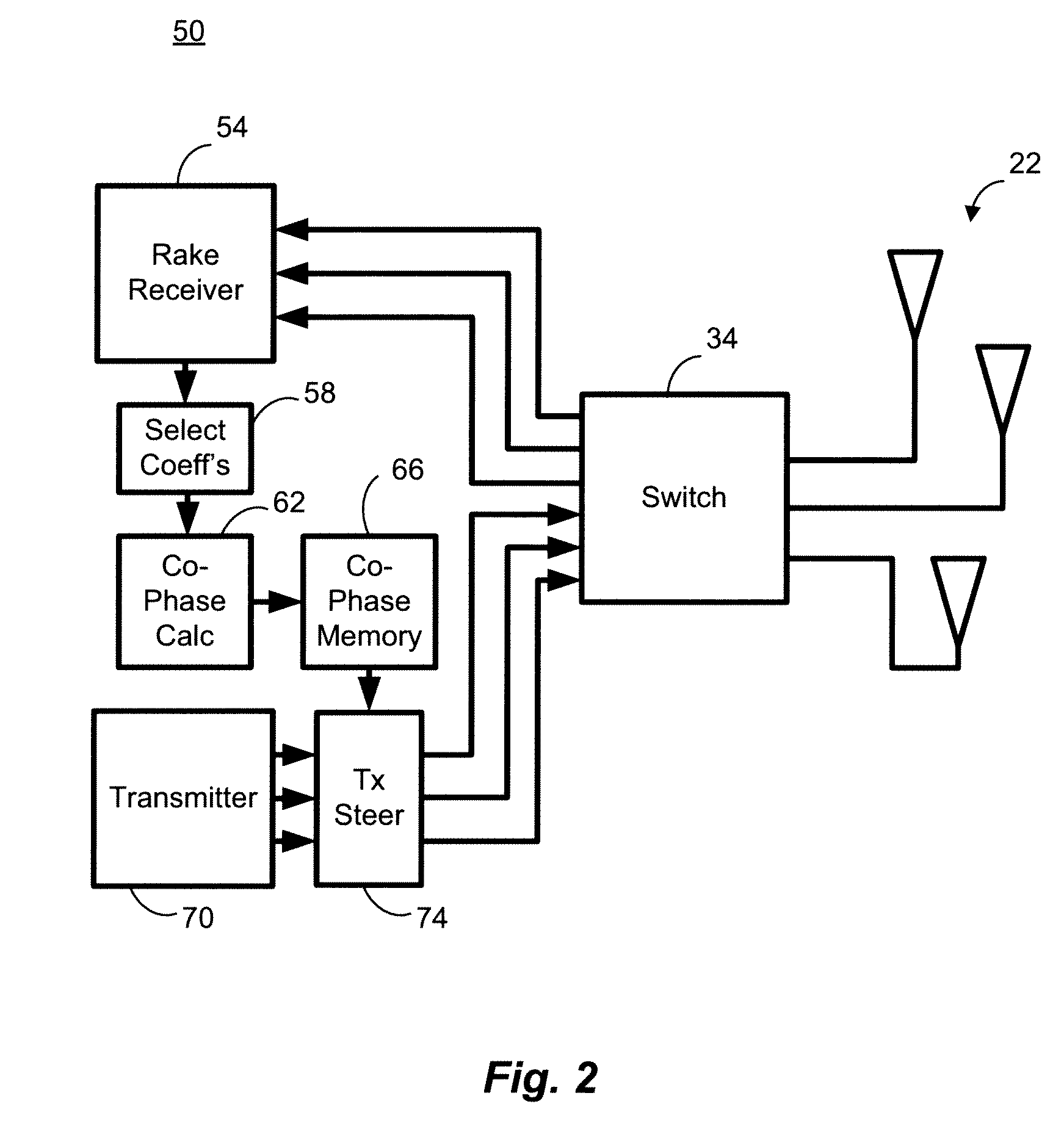
A rake receiver having a plurality of rake fingers is adapted based on a plurality of received signals. The plurality of received signals correspond to a single signal transmitted by a single antenna transceiver and received by a multiple antenna transceiver that includes the rake receiver. Each of a plurality of groups of rake fingers corresponds to a single-input, multiple output (SIMO) channel estimate. One coefficient from each of the plurality of SIMO channel estimates is selected, and a transmit steering vector is calculated based on the selected coefficients. The transmit steering vector is applied to a signal to be transmitted by the multiple antenna transceiver to the single antenna transceiver.

Description

CROSS-REFERENCES TO RELATED APPLICATIONS[0001]The present application claims the benefit of U.S. Provisional Application No. 60 / 908,989, entitled “Transmit Beamforming for SDD / CCK (802.11b) Systems with Multiple Transmit Antennas,” filed on Mar. 30, 2007, which is hereby incorporated by reference herein in its entirety.[0002]The present application also claims the benefit of U.S. Provisional Application No. 60 / 939,712, entitled “Transmit Beamforming for DSSS / CCK (802.11b) Systems with Multiple Transmit Antennas,” filed on May 23, 2007, which is hereby incorporated by reference herein in its entirety.FIELD OF THE DISCLOSURE[0003]The present disclosure relates generally to wireless communication systems and, more particularly, to a method and apparatus for transmit beamforming while transmitting information via a multiple-input, single-output wireless communication channel.BACKGROUND[0004]An ever-increasing number of relatively cheap, low power wireless data communication services, ne...

Claims


Application Information

Patent Timeline
Patent Type & Authority Patents(United States)
IPC IPC(8): H04B7/12H04L1/02H04L27/00
CPCH04B7/0617H04B1/707H04B7/086
Inventor ZHANG, HONGYUANYANG, ZHIYU
Owner MARVELL ASIA PTE LTD
Learn More