Thermal powerline rating and clearance analysis using thermal imaging technology

a technology of thermal imaging and powerline, applied in the direction of heat measurement, speed/acceleration/shock measurement, instruments, etc., can solve the problems of direct limit of the conductor's capacity, difficult to predict wind speed and direction, and generate a significant margin of error, so as to minimize the impact of sun reflection

Active Publication Date: 2013-02-12
HUDSON POWER TECH LLC
View PDF20 Cites 233 Cited by
  • Summary
  • Abstract
  • Description
  • Claims
  • Application Information

AI Technical Summary

Benefits of technology

[0020]The thermal sensor may comprise an infrared camera, a thermal line scanner, or other thermal measurement device. The apparatus may further include a thermal band filter that minimizes impact of sun reflection from the conductor, and / or a sky thermometer that measures atmospheric temperature in a direction that thermal radiation may be reflected from the conductor towards the thermal sensor, and the data processor may employ the measured atmospheric temperature in determining the temperature of the conductor.

Problems solved by technology

Especially, prediction of wind speed and direction are difficult to perform due to turbulence and high variation of wind speeds.
Due primarily to weather variables, this practice can generate a significant margin of error.
The associated uncertainty of a conductor's temperature directly limits its capacity.
As current flow through conductors increases, the temperature of the conductors increases, causing them to elongate.
Beyond certain “maximum allowable” sag, the lines may flashover, resulting in a power supply outage or injury to the public or property damage.
Additionally, if conductor temperature remains high for an extended period of time, the strength of the conductors and tensioned connectors may decrease, which could trigger mechanical failure during the next occurrence of ice or high wind loading.

Method used


Image

  • Thermal powerline rating and clearance analysis using thermal imaging technology
  • Thermal powerline rating and clearance analysis using thermal imaging technology
  • Thermal powerline rating and clearance analysis using thermal imaging technology

Examples


Embodiment Construction

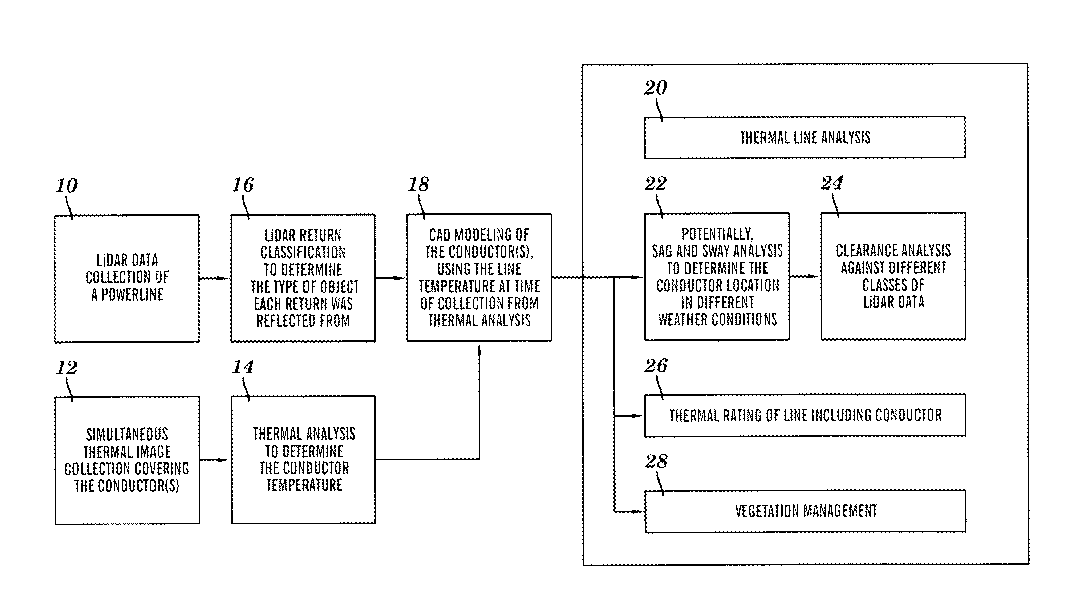
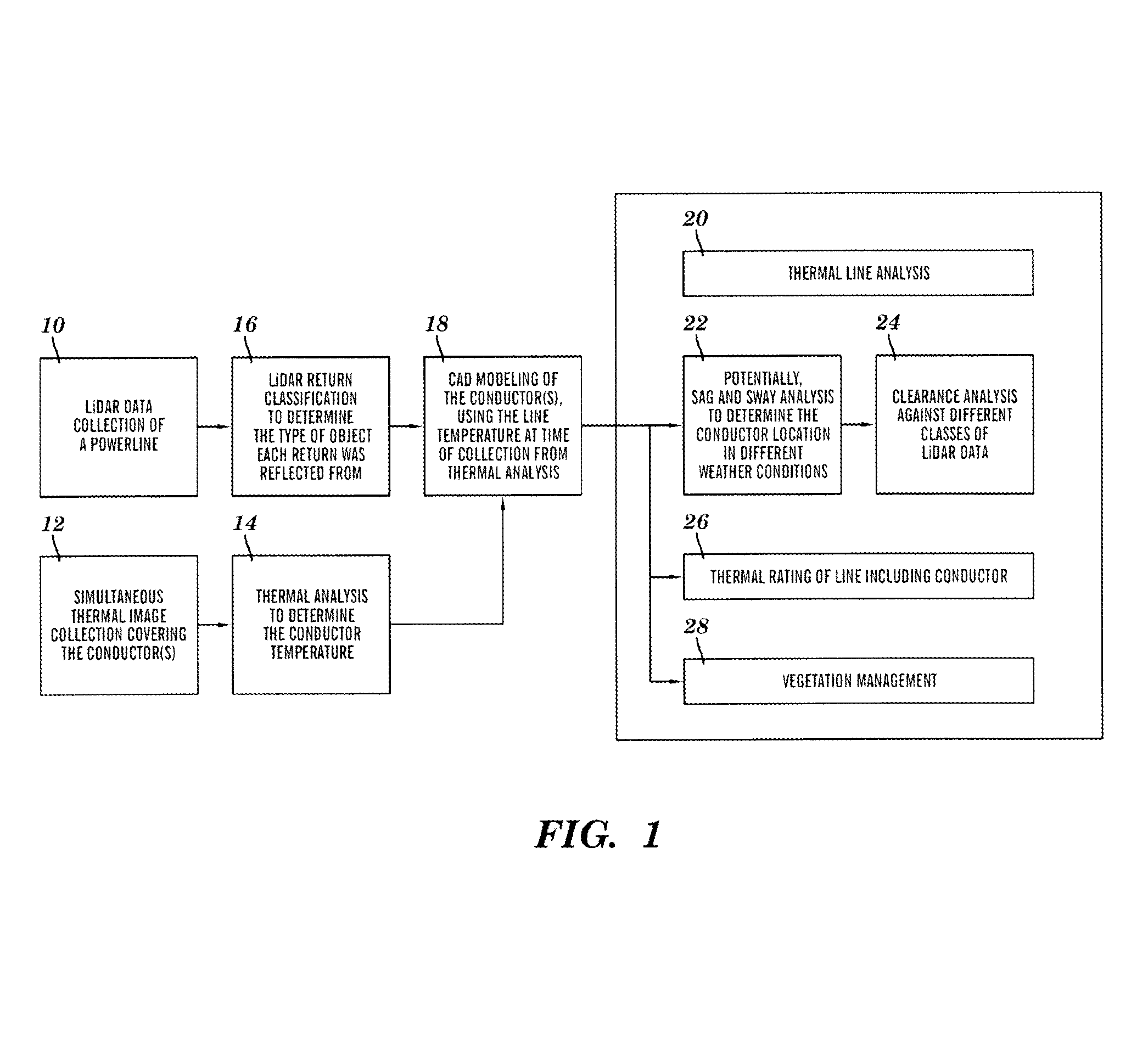
[0033]FIG. 1 provides an overview of a method for thermal line analysis of an overhead electrical conductor in accordance with the principles of the present invention. The method may include the following steps.

LiDAR Data Collection of a Powerline (10)

[0034]Collecting LiDAR data over a powerline is a process well known to the industry.

Simultaneous Thermal Image Collection Covering the Conductor(s) (12)

[0035]Simultaneous collection of thermal measurements of the conductor temperature may be accomplished according to the process described in detail below.

Thermal Analysis to Determine the Conductor Temperature (14)

[0036]Thermal analysis to determine the conductor temperature may be accomplished according to the process described in detail below.

LiDAR Return Classification (16)

[0037]LiDAR return classification is a process well known in the industry to determine the type of object each return was reflected from. There are commercial products, for example, TerraScan® software, available ...


PUM

PropertyMeasurementUnit
operating temperatureaaaaaaaaaa
focal lengthaaaaaaaaaa

Abstract

A method and apparatus are provided to acquire direct thermal measurements, for example, from a LiDAR collecting vehicle or air vessel, of an overhead electrical conductor substantially simultaneous with collection of 3-dimensional location data of the conductor, and utilize temperature information derived from the direct thermal measurements in line modeling, line rating, thermal line analysis, clearance analysis, and / or vegetation management.

Description

CROSS REFERENCE TO RELATED APPLICATIONS[0001]This application is related to commonly assigned, concurrently filed application Ser. No. 13 / 212,689, now U.S. Pat. No. 8,275,570, filed Aug. 18, 2011, and claims priority of U.S. provisional application Ser. No. 61 / 426,037 filed on Dec. 22, 2010, Ser. No. 61 / 448,236 filed on Mar. 2, 2011, and Ser. No. 61 / 495,694 filed on Jun. 10, 2011, the entire contents of these applications being hereby incorporated by reference herein.BACKGROUND ARTBackground[0002]This invention relates generally to the field of powerline management, and, more particularly to a new approach that directly determines temperature of an overhead electrical conductor at time of 3-dimensional location data collection, for use in such applications as CAD modeling of the conductor, thermal line analysis of the conductor, thermal rating of a power line that includes the conductor, clearance analysis relative to the conductor, vegetation management relative to the conductor, a...

Claims


Application Information

Patent Timeline
Patent Type & Authority Patents(United States)
IPC IPC(8): G01K17/02G01K17/06G01C5/02G01K17/14
CPCH02G1/02H02G7/00G01K13/00G06F17/00G06F17/50G06F30/00
Inventor ROUSSELLE, ADAM ROBERTLEPPPANEN, VESA JOHANNESBRZYS, KEVINCLYMER, HUGH ANDREWSMITH, DAWN MARIE
Owner HUDSON POWER TECH LLC
Why Eureka
Try Eureka