Heat exchanger comprising tubes with grooved fins

a heat exchanger and tube technology, applied in the direction of heat exchange apparatus, tubular elements, heat exchangers, etc., can solve the problems of not enabling a good cooling of the fins, the area of the tubes located at the rear of the tubes in the direction of air flow, etc., to achieve the effect of increasing heat exchange and reducing pressure drop

Active Publication Date: 2013-02-19
GEA BATIGNOLLES TECH THERMIQUES
View PDF24 Cites 8 Cited by
  • Summary
  • Abstract
  • Description
  • Claims
  • Application Information

AI Technical Summary

Benefits of technology

[0007]The aim of the invention is to propose a grooved fin structure for heat exchanger tube that makes it possible to obtain an increase in heat exchanges between the air and the fluid circulating in the tube, without deteriorating the pressure drop.
[0009]The main advantage of such a tiered conformation of the relief of the fins is that it makes it possible to better guide the flow of air to the rear of the tubes in the radial direction of the tubes (in the direction of the flow that arrives on the tubes). By using tubes with external fins according to the invention, it is thereby possible to considerably reduce a recirculation zone of the air to the rear of the tubes in the direction of the air flow, normally considerable when finned tubes without relief (flat profile) are used. Thus, the tiered relief surface guiding the air to the rear of the tubes makes it possible to reduce the recirculation zones where the heat exchange is poor and thus to take better advantage of the surface of the fins. In this way, with a fin according to the invention, the gain obtained in terms of thermal performance can be very significant.

Problems solved by technology

Thus, due to the structure of the flow and the exchanger, the areas of the tubes located at the rear of the tubes in the direction of the air flow are practically unexploited for the heat exchange.
Said areas, known as recirculation zones, of the exchanger are characterized by a recirculation of the air, which generates pressure drops and which does not enable a good cooling of the fin.
However, since heat exchangers are usually outside and since the ambient air is not filtered, the cut outs formed in the fin may act as sources of fouling due to dust, insects, etc., which obstruct the cut outs.

Method used


Image

  • Heat exchanger comprising tubes with grooved fins
  • Heat exchanger comprising tubes with grooved fins
  • Heat exchanger comprising tubes with grooved fins

Examples


Embodiment Construction

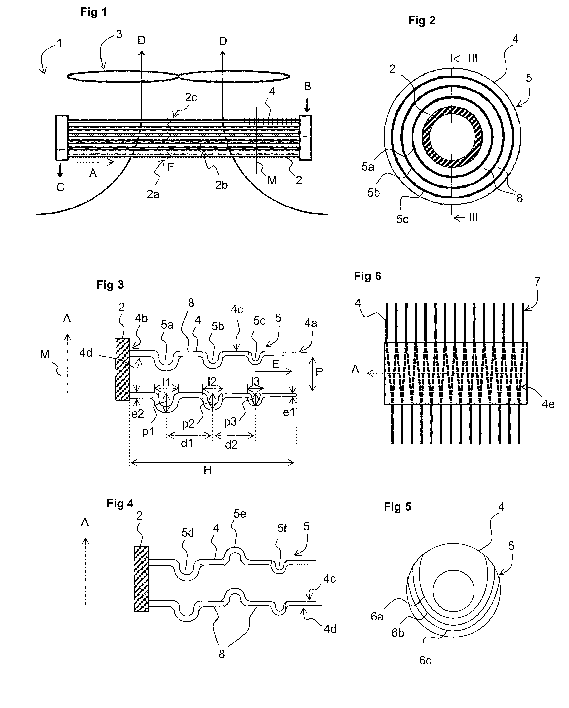
[0024]In FIG. 1, a heat exchanger 1 has been represented comprising a bundle of tubes 2 of circular section with fins arranged in several substantially parallel superimposed rows extending in an axial direction A in which a fluid to be cooled circulates between an inlet B and an outlet C of the fluid, and around which circulates a flow of drafted ambient air drawn from the bottom upwards in the direction indicated by the arrows D, in a transversal manner to the tubes 2, by fans 3 positioned above the heat exchanger 1. The circulation of the fluid is here divided up into three successive passage sections or passes 2a, 2b,2c schematically represented in FIG. 1, which makes it possible to improve the cooling of the fluid. A heat exchanger 1 thus generally comprises between three and eight rows of superimposed tubes 2 laid out in a staggered manner or aligned in relation to the direction of circulation of the fluid in the tubes 2 as indicated by the arrows F.

[0025]The tubes 2 are provid...


PUM


Abstract

Tube heat exchanger comprising finned tubes, wherein the tubes extend in a certain axial direction and are provided with heat exchange fins. Each fin has a heat exchange surface surrounding a tube that extends in a certain radial direction in relation to the tube and which is relief structured to form grooves spaced apart from one another in said radial direction. The grooves of a fin have different dimensions that decrease on moving away from the tube in said radial direction so as to form a guide for a fluid around the tube.

Description

FIELD OF THE INVENTION[0001]The invention relates to a tube heat exchanger comprising finned tubes, wherein the tubes extend in a certain axial direction and are provided with heat exchange fins, each fin having a heat exchange surface surrounding a tube that extends in a certain radial direction in relation to the tube and which is relief structured to form grooves spaced apart from one another in said radial direction.[0002]More specifically, the invention applies to a tube heat exchanger employing air as secondary exchange fluid such as an air cooling, air condensing, air heating or air evaporating type equipment, used respectively for cooling, condensing, heating and evaporating a fluid, particularly in refining processes, gas treatment and compression plants, gas liquefaction units, coal and gas synthesis units, electricity production installations, regasification units, or any other fluid treatment installation.PRIOR ART[0003]Generally speaking, such equipment comprises a main...

Claims


Application Information

Patent Timeline
Patent Type & Authority Patents(United States)
IPC IPC(8): F28F13/02F28F1/36
CPCF28F1/24F28F13/06F28F2215/10
Inventor ROBIDOU, HERVELINEGOUMONDIE, JEROMETINTILLIER, REMYCLUNET, FRANCOISCHACUN, SERGE
Owner GEA BATIGNOLLES TECH THERMIQUES
Why Eureka
Try Eureka