
Method for automatically producing a defined face opening in plow operations in coal mining

a technology of face opening and plow operation, which is applied in the direction of mining structures, mine roof supports, slitting machines, etc., can solve the problems of difficult control of radio conditions, method is primarily fragile on the hardware side, and is too imprecise to be able to support automatic control of extraction and support work thereon, so as to eliminate errors caused by vibration of components

Inactive Publication Date: 2013-02-19
RAG AG
View PDF18 Cites 14 Cited by
  • Summary
  • Abstract
  • Description
  • Claims
  • Application Information

AI Technical Summary

Benefits of technology

The invention provides a method for controlling the height of a plow in mining based on the angle of inclination of the face conveyor. This angle is measured and used to determine the difference between the top canopy of the shield support frame and the face conveyor. This difference is incorporated in the calculation of the face opening to be produced by the plow, which allows for height control of the plow so that the predefined target height of the face opening is achieved. The method is guided on an intact boundary layer at the overlying stratum, which typically does not impair its course, while the floor skid frequently does not travel on the natural footwall, but rather along the level which is exposed by the floor chisels of the plow. The invention also utilizes acceleration sensors that detect the angle of inclination of the shield components to the horizontal, which can be corrected using a suitable damping method to eliminate errors caused by vibrations of the components used.

Problems solved by technology

A problem in the automatic control of longwall operations both in the mining direction and also in the extraction direction of the extraction machine used is, inter alia, producing a sufficiently large face opening to ensure the passage of the longwall equipment without collisions between extraction machine and shield support frames as the extraction machine travels past, for example, on the one hand, and keeping the rock collapse during the extraction work as limited as possible, and accordingly restricting the extraction work to the coal layer as much as possible, without also cutting excessive country rock, on the other hand.
The mineral deposit data which is essentially available before the extraction about seam thickness, level of footwall or overlying stratum, and the presence of saddles and / or troughs both in the mining direction and also in the longitudinal direction of the longwall equipment, i.e. in the extraction direction of the extraction machine, are too imprecise to be able to support automated control of the extraction and support work thereon.
This problem results in particular in the case of so-called plow operations, during which a plow moves back and forth along the longwall front on a fixed guide attached to the face conveyor.
This method is primarily fragile on its hardware side, because the relevant sensor and the associated evaluation computer are installed in an extremely rough environment in or on the plow and are thus subject to corresponding stresses and / or occurring defects.
Furthermore, the mobility of the plow requires a power supply of the hardware via battery and a data transmission via radio using multiple transponders situated in the longwall, the radio conditions being very difficult to control in particular in low longwalls having higher proportions of ferromagnetic components of the longwall equipment.
In addition, this method is also subject to uncertainties in its information and / or also causes a corresponding time delay in the case of possibly required regulation, because a somewhat reliable statement about the material cut by the plow is only to be made after several plow passes, i.e., after it travels past a shield support frame several times, typically approximately 5 times.

Method used


Image

  • Method for automatically producing a defined face opening in plow operations in coal mining
  • Method for automatically producing a defined face opening in plow operations in coal mining
  • Method for automatically producing a defined face opening in plow operations in coal mining

Examples


Embodiment Construction

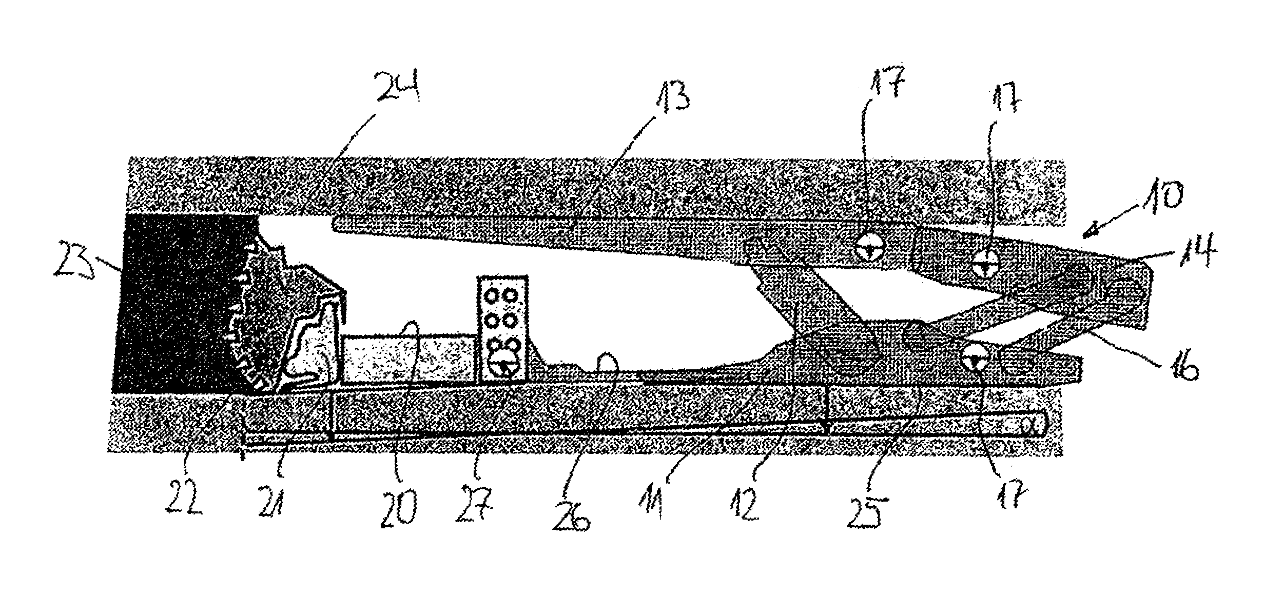
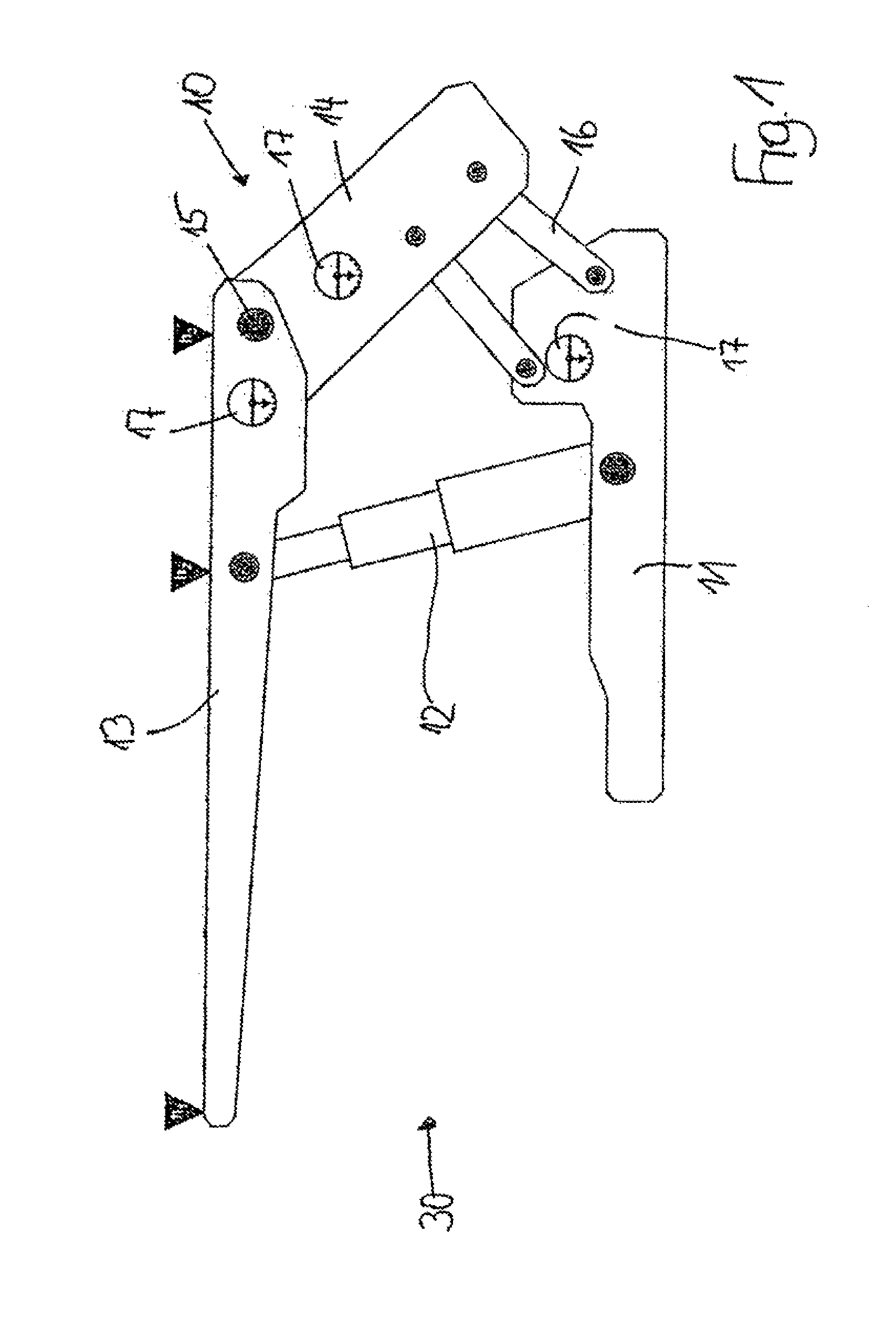
[0028]The shield support frame 10 shown in FIG. 1 comprises a floor skid 11, on which two props 12 are placed in parallel configuration, of which only one prop is recognizable in FIG. 1, which carries a top canopy 13 on its upper end. While the top canopy 13 protrudes at its front (left) end in the direction of the extraction machine (to be described hereafter), a gob shield 14 is linked using a joint 15 on the rear (right) end of the top canopy 13, the gob shield being supported by two supporting connection rods 16, which rest on the floor skid 11 in the side view. In the exemplary embodiment shown, three inclination sensors 17 are attached to the shield support frame 10, one inclination sensor 17 on the floor skid 11, one inclination sensor 17 in the rear end of the top canopy 13 in proximity to the joint 15, and one inclination sensor 17 on the gob shield 14. As is not shown in greater detail, an inclination sensor can also be provided on the fourth movable component of the shiel...


PUM


Abstract

A method for automatically producing a defined face opening in a longwall mining operation in underground coal mining, using a face conveyor, at least one plow, as an extraction machine, guided on the face conveyor, and respective hydraulic shield support frames having, as main components, a floor skid arrangement, a gob shield, a top canopy and support connection rods. Inclination sensors are disposed on at least three of the floor skid arrangements, the gob shield, the support connection rods and a gob-side region of the top canopy. From the sensors, an inclination relative to a horizontal is ascertained. From the inclination data, by comparison with base data defining a geometrical orientation of the components and movement thereof during a stepping process, a respective shield height of the shield support frames perpendicular to a bed thereof is calculated and is compared with a machine-dependent fixed cutting height of the plow to establish if deviations exist. By means of a boom controller disposed between the shield support frame and the face conveyor, a height control of the plow is initiated to correct established deviations and is maintained, in the sense of a location-synchronized evaluation, until the shield support frame, which trails the plow with a time delay, has reached the position at which the plow was located at the point in time when the height control of the plow was initiated.

Description

BACKGROUND OF THE INVENTION[0001]The instant application should be granted the priority date of Feb. 19, 2008, the filing date of the corresponding International patent application PCT / EP2008 / 001268.[0002]The invention relates to a method for automatically producing a defined face opening in the case of longwall operations, comprising a face conveyor, at least one plow guided on the face conveyor as an extraction machine, and a hydraulic shield support, in underground mining.[0003]A problem in the automatic control of longwall operations both in the mining direction and also in the extraction direction of the extraction machine used is, inter alia, producing a sufficiently large face opening to ensure the passage of the longwall equipment without collisions between extraction machine and shield support frames as the extraction machine travels past, for example, on the one hand, and keeping the rock collapse during the extraction work as limited as possible, and accordingly restricti...

Claims


Application Information

Patent Timeline
IPC IPC(8): E21C35/14
CPCE21C35/14E21C35/24E21D23/0004E21D23/12E21D23/0039E21D23/0043E21D23/0034
Inventor JUNKER, MARTINMOZAR, ARMIN
Owner RAG AG
Learn More