
Termination cap for use in wired network management system

a technology of termination cap and management system, which is applied in the direction of stacked spaced pcbs, coupling device connections, printed circuit aspects, etc., can solve the problems of presenting problems to the it management group, difficult and time-consuming operation of adding, removing or tracing patch cords, etc., and achieves the effect of facilitating the inventorying of the network

Inactive Publication Date: 2013-02-19
MOLEX INC
View PDF23 Cites 10 Cited by
  • Summary
  • Abstract
  • Description
  • Claims
  • Application Information

AI Technical Summary

Benefits of technology

The present invention provides an improved system for monitoring a network with multiple work area outlets to which are connected various end-user devices. The system facilitates the inventorying of the network and monitoring of end-user devices by using a termination cap with a sensing element that connects with selected terminals of two distinct differential signal wire pairs of a work area outlet, and the sensing value affects the impedance of the system. This makes it easy to determine when an end-user device is connected to the network at a specific location on the network.

Problems solved by technology

The management of the patch cords in the telecom room or at the work area outlet can present issues to the IT management group.
Each time an employee is hired, leaves the organization or changes location, it is inevitable that patch cables must be connected and disconnected.
The patch cords are often snaked around one another, making the operations of adding, removing, or tracing the patch cords difficult and time-consuming.
Once the patch cord is connected, there is not an easy, cost and time-effective way to determine if the cord was connected to the correct port(s).
Therefore, connecting and transferring networks assets is labor-intensive.
Additionally, the IT department does not have an efficient way to determine the exact location of network problems which may be attributed to the physical layer.
For example, the problem may be located in the switch closet if a patch cord was not properly connected, or the problem may exist in the wiring from the switch closet to the end-user device.
The IT department does not currently have an efficient way to determine if network problems exist in the physical network wiring.
An additional area of concern is that the LAN may have substantial numbers of unused or spare permanent links.
An issue facing IT managers today is that it is difficult and time consuming to re-test spare permanent links to verify connectivity prior to their being put into use.
Consequently most spare permanent links are not tested on a regular basis, and if there is a problem with the connectivity of the link, the issue may not be discovered until the permanent link is activated as part of a working channel.
This can cause delay and added expense as the problem is tracked down and repaired.

Method used


Image

  • Termination cap for use in wired network management system
  • Termination cap for use in wired network management system
  • Termination cap for use in wired network management system

Examples


Embodiment Construction

[0044]The following description is intended to convey the operation of exemplary embodiments of the invention to those skilled in the art. It will be appreciated that this description is intended to aid the reader, not to limit the invention. As such, references to a feature or aspect of the invention are intended to describe a feature or aspect of an embodiment of the invention, not to imply that every embodiment of the invention must have the described.

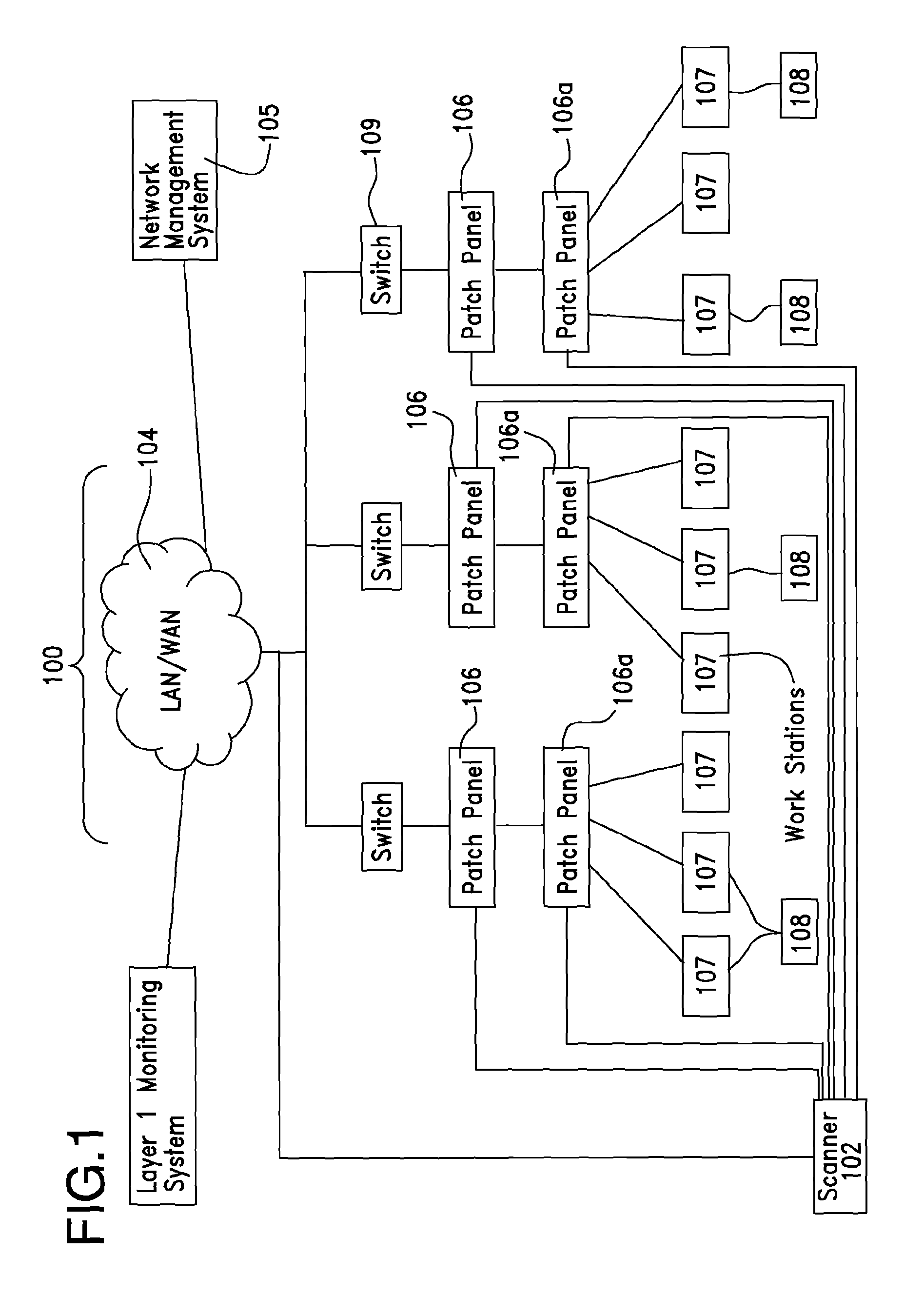
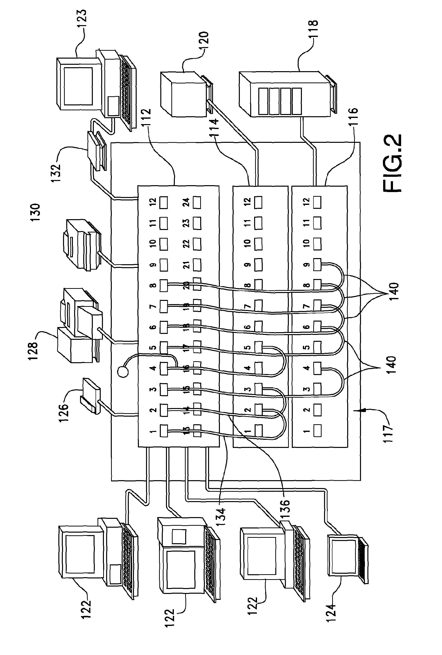
[0045]Turning to the drawings and referring first to FIG. 1, a typical computing, or data transmission, network 100 is illustrated to show the environment in which the patch panel assemblies of the present invention are used. An example of such a data network is a corporate electronic computing network with multiple users and network and end-user devices connected thereto by which network users can access, exchange and store data. As used herein, the term “end-user device” refers to a physical item that is connected to a work area o...


PUM


Abstract

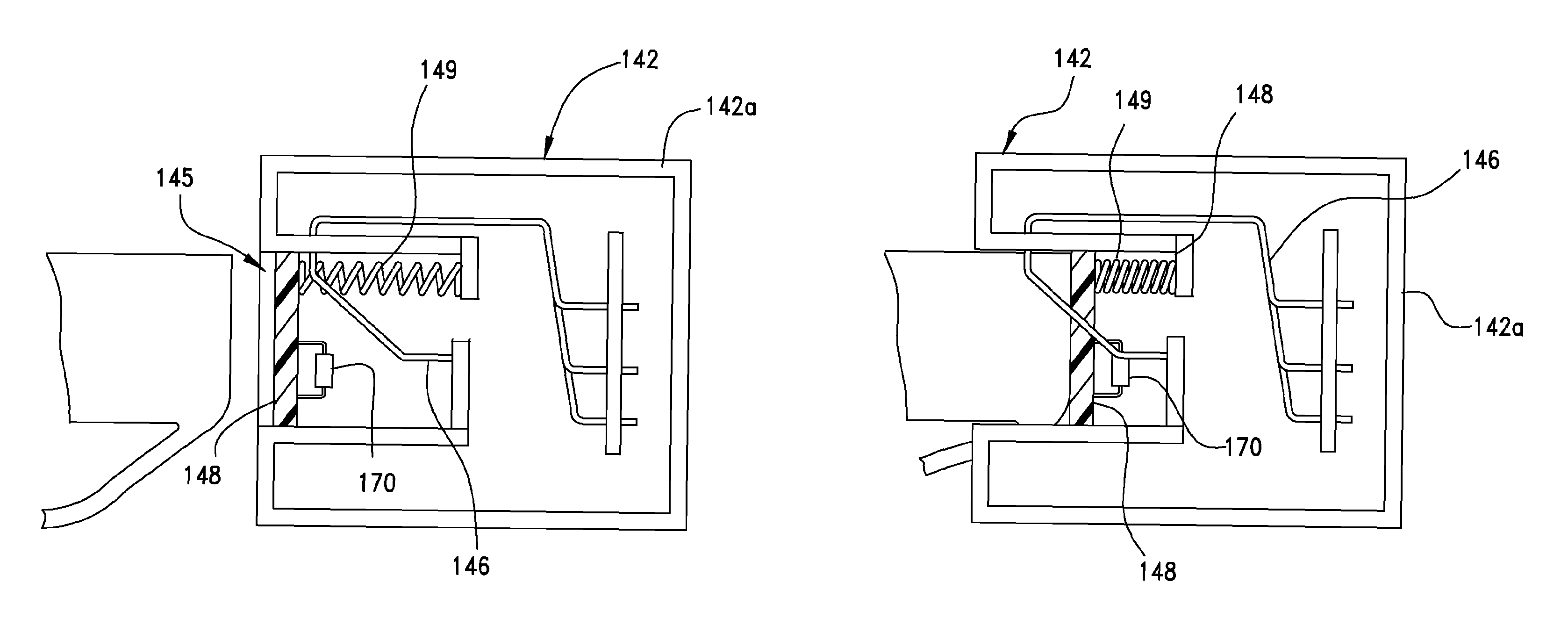
A termination unit (144) for use with a system that permits the monitoring of a computer network to perform network inventories. The termination unit takes the form of a cap that engages the termination face of a network jack and has a sensing circuit (246) integrated therewith so that, once engaged with the jack, the sensing circuit is connected to two terminals of the jack. The sensing circuit may include a resistor, capacitor or inductor, any of which provide a known sensing value that is different than a sensed value of an end-user device used on the network, but less than infinity so that the system senses when an end-user device is connected to or disconnected from the network.

Description

CROSS-REFERENCES TO RELATED APPLICATIONS[0001]The present invention claims the priority of previously-filed U.S. Provisional Application Nos. 61 / 103,487 and 61 / 103,532, both of which were filed on 7 Oct. 2008. The contents of each of these previously-filed Applications are incorporated by reference herein in their entireties.BACKGROUND OF THE INVENTION[0002]The present invention relates generally to infrastructure management systems and, more particularly, to systems, assemblies and components that are useful in managing infrastructure assets.[0003]Computing networks that exist within large organizations consist of two types of devices that must be inter-connected to form a usable data network. These devices, which are also referred to in the art as assets, are generally classified as end-user devices and networking devices. Examples of end-user devices include personal computers (PC), voice-over-internet protocol (VoIP) phones, and network printers. A typical Local Area Network (LA...

Claims


Application Information

Patent Timeline
Patent Type & Authority Patents(United States)
IPC IPC(8): H01R24/00
CPCH04L41/12H05K1/144H04Q1/136H05K1/118H05K2201/042H05K2201/10189H05K1/147H05K3/326H05K2201/0311H05K2201/09063H05K2201/09072H05K2201/091H05K2201/09445H01R4/2433H01R13/2421H01R13/6616H01R24/64H01R2201/04H01R13/4538H01R13/465H01R13/6473H01R13/6625
Inventor PANELLA, AUGUSTO P.BAINES, ELLIOT A.LIN, JENG-DE
Owner MOLEX INC
Learn More