Molded skin with electroluminescent elements

a technology of electroluminescent elements and molded skin, which is applied in the direction of manufacturing tools, transportation and packaging, and other domestic objects, can solve the problems of large production steps, large production costs, and difficult use of components, and achieves easy use, good component integration, and the effect of reducing the number of production steps

Inactive Publication Date: 2013-02-19
JOHNSON CONTROLS INTERIORS GMBH & CO KG
View PDF23 Cites 8 Cited by
  • Summary
  • Abstract
  • Description
  • Claims
  • Application Information

AI Technical Summary

Benefits of technology

[0020]Therefore, the object of the invention is to provide a method of producing a plastic skin with electroluminescent elements, which method, on the one hand, minimizes complex production steps, can easily be used in existing production processes and systems, is applicable for all lining components and design sizes and, on the other hand, combines a good component integration with a pleasant appearance of the plastic skin.

Problems solved by technology

Altogether, therefore, considerable effort, a series of time-consuming and cost-intensive production steps, and logistical planning are still required before a ready-to-install dashboard, a door insert, or similar components with functional elements are passed on to the plant carrying out further processing, that is to the vehicle manufacturer.
In particular, in the inclusion of conductors for illuminants, which due to the required current rating have to be designed relatively “thick”, there arises the problem that when joining the two different materials (molded skins or films and conductors) the surface of decorative design, that is, the surface of the plastic skin which is visible from outside, is damaged by the contact pressure.
Furthermore, “thick” conductors will leave marks on the surface of the decorative design if they are laminated at temperatures that are too high and if they are laminated to one another, with the shrinkage of the materials being different, and subsequently cool down at different rates.
Furthermore, there exists the problem that the molded skins or films and the conductors have different heat expansion coefficients when stored in heat, and thus a second conductor which might have been laminated behind the surface of the decorating design becomes visible.
In addition, there exists the problem that certain areas of the surfaces, especially in the case of surfaces that are produced by the slush process (rotational sintering), cause kinks during demolding due to their different degrees of rigidity.
The various necessary positioning and pressing steps in the tools required for this purpose prove to be disadvantageous.
The production of larger parts is rather difficult by this embodiment.

Method used


Image

  • Molded skin with electroluminescent elements
  • Molded skin with electroluminescent elements
  • Molded skin with electroluminescent elements

Examples


Embodiment Construction

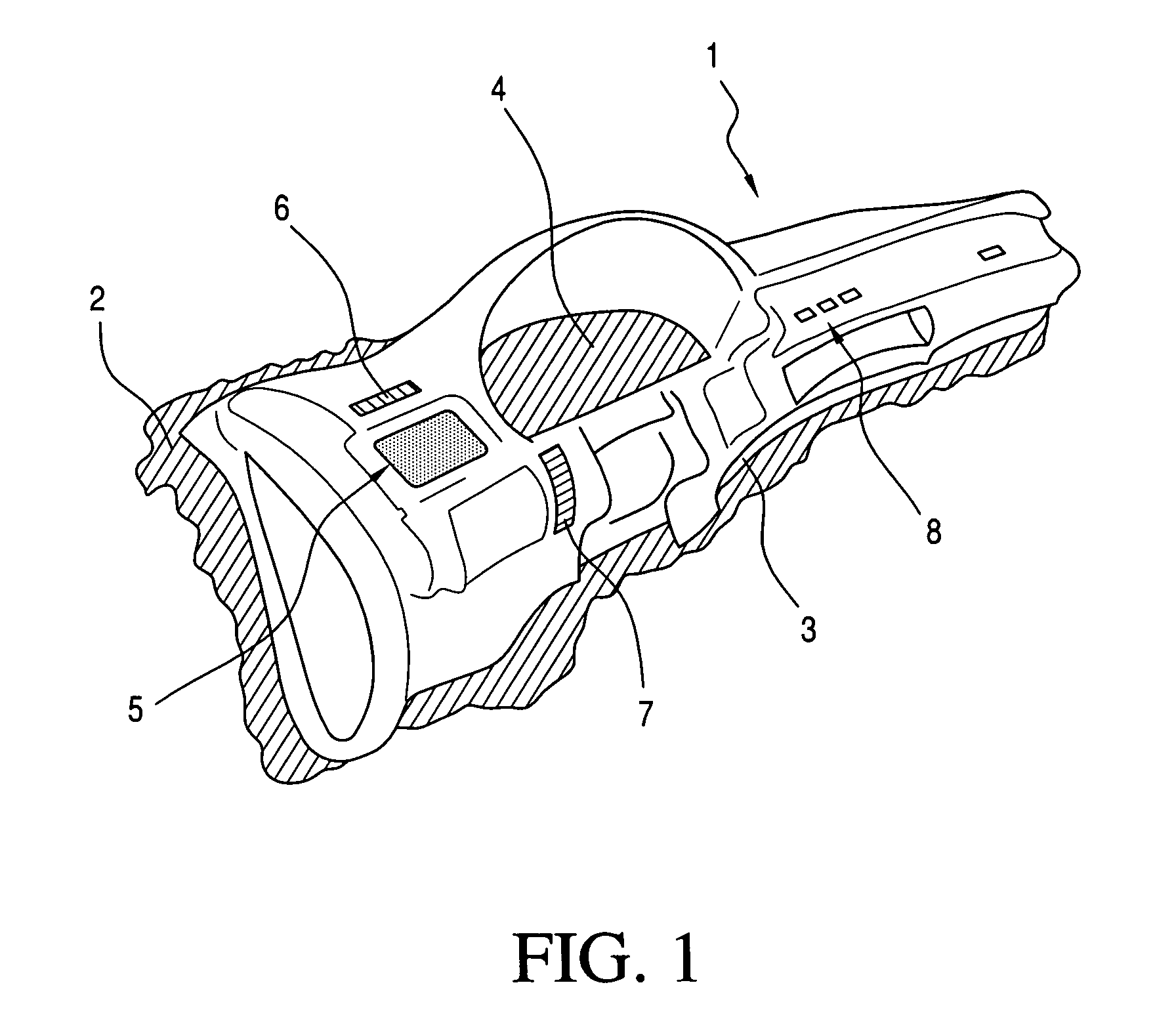
[0043]FIG. 1 shows a molded skin 1 produced in accordance with the method according to the invention, namely a so-called slush skin for the dashboard of a motor vehicle, such as is produced according to the rotational sintering method. As a result, the contour of the dashboard is distinctly configured so that the molded skin can easily be applied to a correspondingly adapted reinforcing sub-construction, a so-called carrier.

[0044]The shaded areas (2, 3) of the molded skin pertain to excess mold edges to be removed in the finishing process. The shaded area 4 is likewise cut out in the finishing process and subsequently forms the recess for the display instruments to be inserted later on.

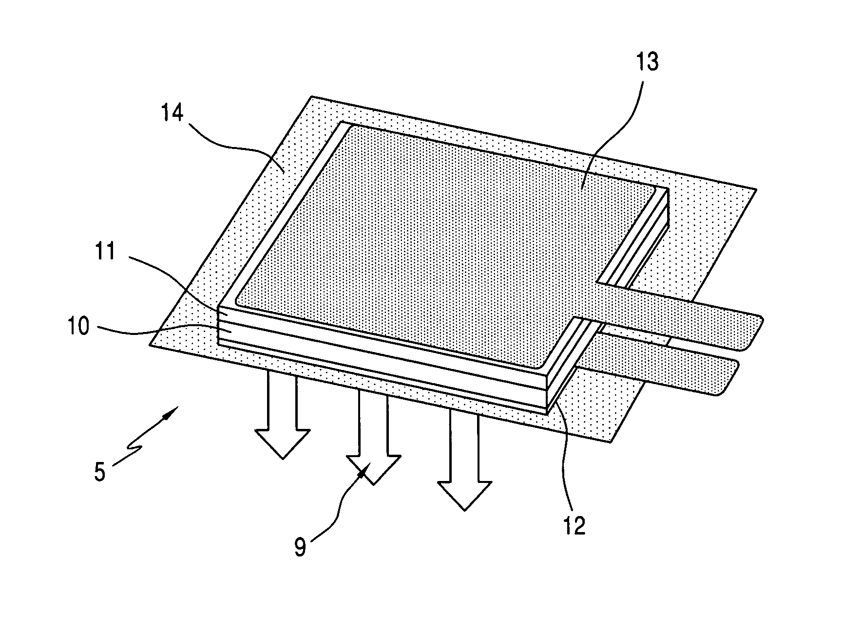
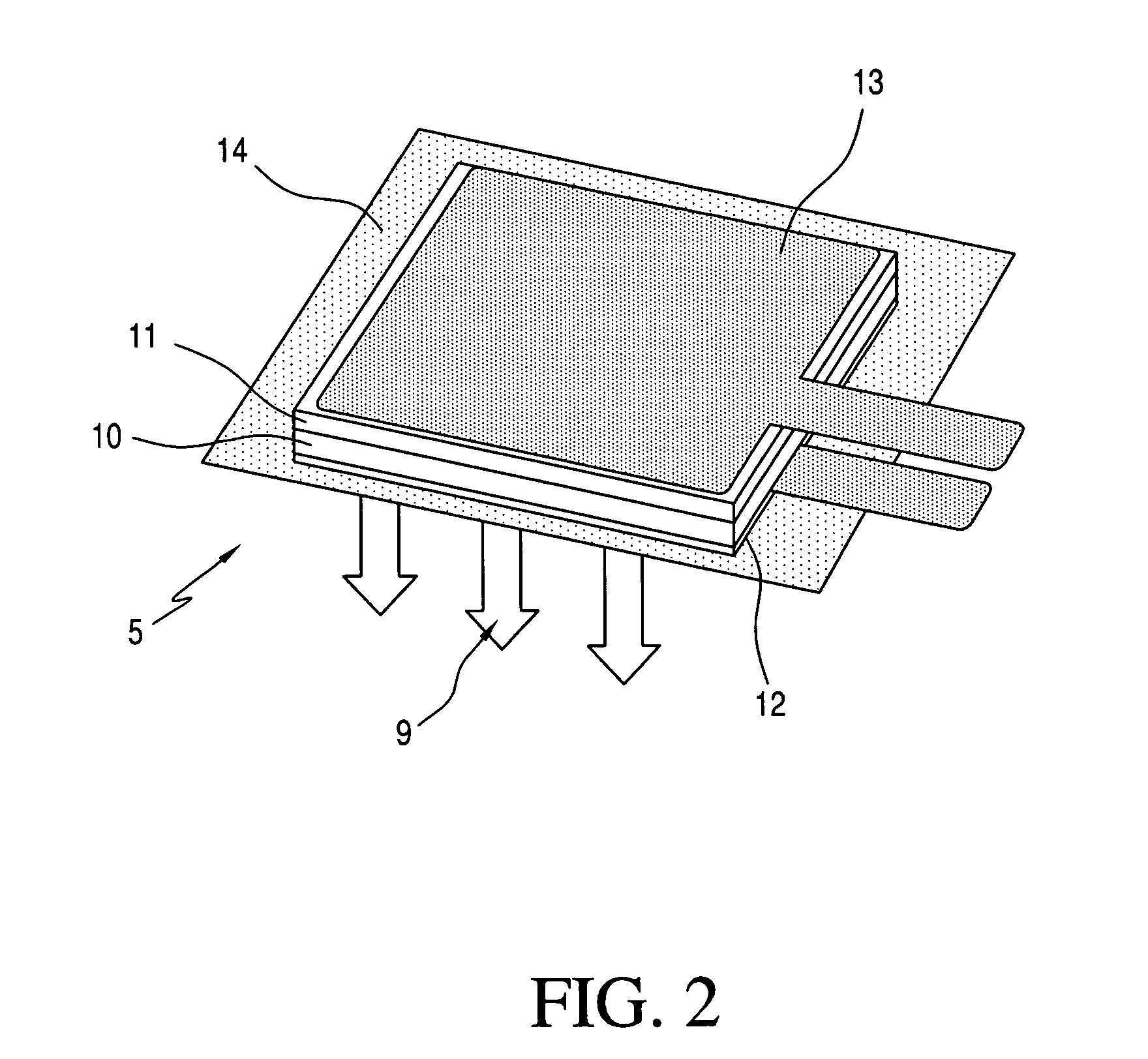
[0045]Embedded in the molded skin are electroluminescent elements for illuminating and signal-transmitting elements 5, 6, 7, and 8, namely for the illuminating element 5, for the signal and information elements 6 and 7 serving as control lamps, and for the “translucently illuminated” lettering 8 formi...


PUM

PropertyMeasurementUnit
temperatureaaaaaaaaaa
voltagesaaaaaaaaaa
alternating voltageaaaaaaaaaa

Abstract

The invention relates to a method for producing an out of tool molded skin (1) with an embedded flat electroluminescent element, wherein an outer function or carrier layer of the electroluminescent element (5, 6, 7, 8) is made of plastic material that is substantially identical to the powdered plastic material of the molded skin and is applied to the not yet fully cured and cooled molded skin.

Description

CROSS REFERENCE TO RELATED APPLICATIONS[0001]This application is a continuation application of international patent application PCT / EP 2009 / 057070, filed Jun. 9, 2009, designating the United States and claiming priority from German application 10 2008 045 015.4, filed Aug. 29, 2008, and the entire content of both applications is incorporated herein by reference.FIELD OF THE INVENTION[0002]The invention relates to a method of producing an out of tool molded skin as a surface covering of coated objects, in which a powdered plastic material is placed in a tool mold or reaction mold and is melted on in the mold in a sintering method, preferably by rotational sintering, whereby the molded skin comprises at least one planar electroluminescent element comprising a plurality of functional and / or carrier layers, wherein the electroluminescent element is embedded in the molded skin and / or is coated with the molded skin.BACKGROUND OF THE INVENTION[0003]Grained, patterned, or finely structured ...

Claims


Application Information

Patent Timeline
Patent Type & Authority Patents(United States)
IPC IPC(8): C09K8/86
CPCB29C41/18B29C41/20B60R13/02B60R13/0256B29K2105/251B60R2013/0287B29L2031/3005
Inventor SOSTMANN, STEFANSEIDEL, CHRISTIAN
Owner JOHNSON CONTROLS INTERIORS GMBH & CO KG
Why Eureka
Try Eureka