Laminate armor and related methods

a technology of laminated armor and abrasives, applied in the field of laminated armor, can solve the problems of adiabatic shear plugging failure of relativly thick monolithic titanium 6al-4v plates

Inactive Publication Date: 2013-02-26
BATTELLE ENERGY ALLIANCE LLC
View PDF21 Cites 5 Cited by
  • Summary
  • Abstract
  • Description
  • Claims
  • Application Information

AI Technical Summary

Problems solved by technology

Research by the U.S. Army Research Lab, however, indicates that relatively thick monolithic titanium 6Al-4V plate suffers from adiabatic shear plugging failures.

Method used


Image

  • Laminate armor and related methods
  • Laminate armor and related methods
  • Laminate armor and related methods

Examples


Embodiment Construction

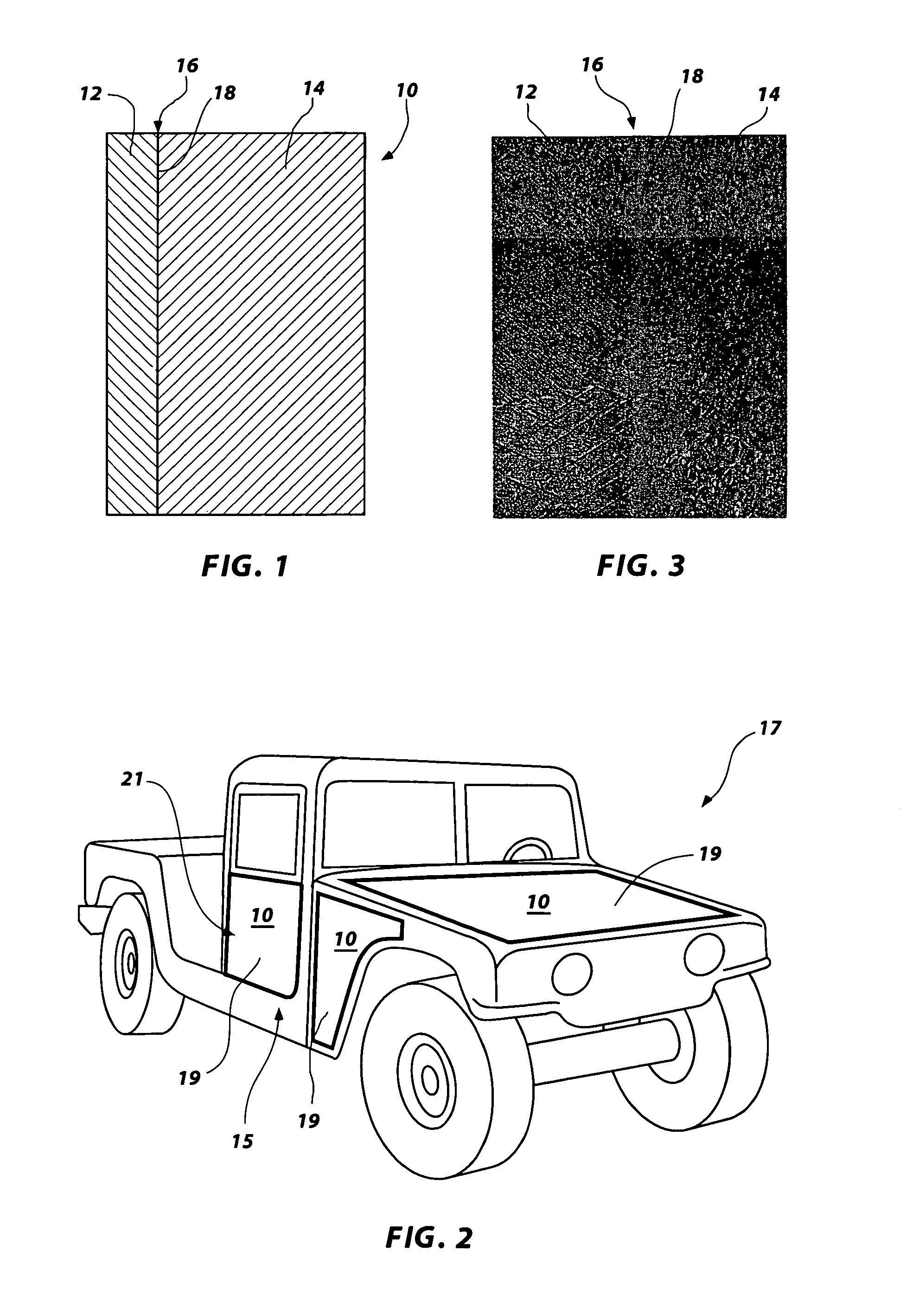
[0017]A cross-sectional view of an armor plate 10 according to an embodiment of the present invention is shown in FIG. 1. The armor plate 10 comprises a plurality of layers, including an outer layer 12 and an inner layer 14. The outer layer 12 may be positioned and configured to receive the initial impact from a projectile and the inner layer 14 may be positioned adjacent the outer layer 12 and may be contiguous with the outer layer 12. As used herein, the term “outer” is indicative of a relative position of layer 12 of armor plate 10 as placed in use to receive a projectile impact, while the term “inner” is indicative of a relative position of layer 14 of armor plate 10 as placed in use facing an area to be protected, for example, a volume containing personnel or material to be protected by armor comprising a laminate according to an embodiment of the present invention. For example, and as shown in FIG. 2, the armor plate 10 may be included in a protective structure, such as a vehi...


PUM

PropertyMeasurementUnit
temperatureaaaaaaaaaa
total thicknessaaaaaaaaaa

Abstract

Laminate armor and methods of manufacturing laminate armor. Specifically, laminate armor plates comprising a commercially pure titanium layer and a titanium alloy layer bonded to the commercially pure titanium outer layer are disclosed, wherein an average thickness of the titanium alloy inner layer is about four times an average thickness of the commercially pure titanium outer layer. In use, the titanium alloy layer is positioned facing an area to be protected. Additionally, roll-bonding methods for manufacturing laminate armor plates are disclosed.

Description

GOVERNMENT RIGHTS[0001]This invention was made with government support under Contract Number DE-AC07-05ID 14517 awarded by the United States Department of Energy. The government has certain rights in the invention.TECHNICAL FIELD[0002]The present invention, in various embodiments, relates to laminate armor and methods of manufacturing laminate armor. Specifically, the invention relates to laminate armor plates comprising a commercially pure titanium layer and a titanium alloy layer wherein, in use, the commercially pure titanium layer may be positioned toward a direction of potentially incoming, hostile projectiles. Additionally, the invention relates to manufacturing laminate armor plates using roll-bonding methods.BACKGROUND[0003]Titanium 6Al-4V alloy has been identified as the material of choice for lightweight combat and tactical vehicles because of its high mechanical strength, high hardness, low density, good formability and high ballistic performance. Research by the U.S. Arm...

Claims


Application Information

Patent Timeline
Patent Type & Authority Patents(United States)
IPC IPC(8): F41H5/04B23K20/04B23K20/14
CPCF41H5/045B23K20/04B23K2203/24B23K2103/24
Inventor CHU, HENRY S.LILLO, THOMAS M.ZAGULA, THOMAS M.
Owner BATTELLE ENERGY ALLIANCE LLC
Why Eureka
Try Eureka