All terrain vehicle

a technology for all terrain vehicles and exhaust devices, which is applied in the direction of roofs, jet propulsion mountings, transportation and packaging, etc., can solve the problems of reducing the cooling effect of all terrain vehicles, reducing the cooling effect of exhaust devices, and bending the duct in a steep angle. , to achieve the effect of enhancing the cooling effect of the exhaust devi

Active Publication Date: 2013-02-26
YAMAHA MOTOR CO LTD
View PDF33 Cites 28 Cited by
  • Summary
  • Abstract
  • Description
  • Claims
  • Application Information

AI Technical Summary

Benefits of technology

[0007]In view of the above, preferred embodiments of the present invention an exhaust device of an all terrain vehicle that provides improved cooling regardless of a driving state and a parking state of the vehicle.
[0009]According to a preferred embodiment of the present invention, the communication path is arranged to connect the space positioned behind the radiator and the space in which the exhaust device is disposed. This structure allows air to easily flow from the space positioned behind the radiator to the space in which the exhaust device is disposed. Additionally, the communication path at least partially overlaps with the fan in a front view of the vehicle. Accordingly, when the fan generates airflow, the airflow reaches the communication path via the radiator. As a result, it is possible to enhance cooling of the exhaust device regardless of a driving state and a parking state of the vehicle.

Problems solved by technology

It is difficult for the all terrain vehicle to enhance cooling of the engine unit and the exhaust device disposed rearward of the engine unit because of the structure that the engine unit is disposed rearward of the front panel.
However, the duct is bent in a steep angle.
Therefore, air does not easily flow within the duct in the parked vehicle.
In this case, air does not easily reach the exhaust device disposed rearward of the engine unit.
As a result, it is difficult to enhance cooling of the exhaust device.

Method used


Image

  • All terrain vehicle
  • All terrain vehicle
  • All terrain vehicle

Examples


Embodiment Construction

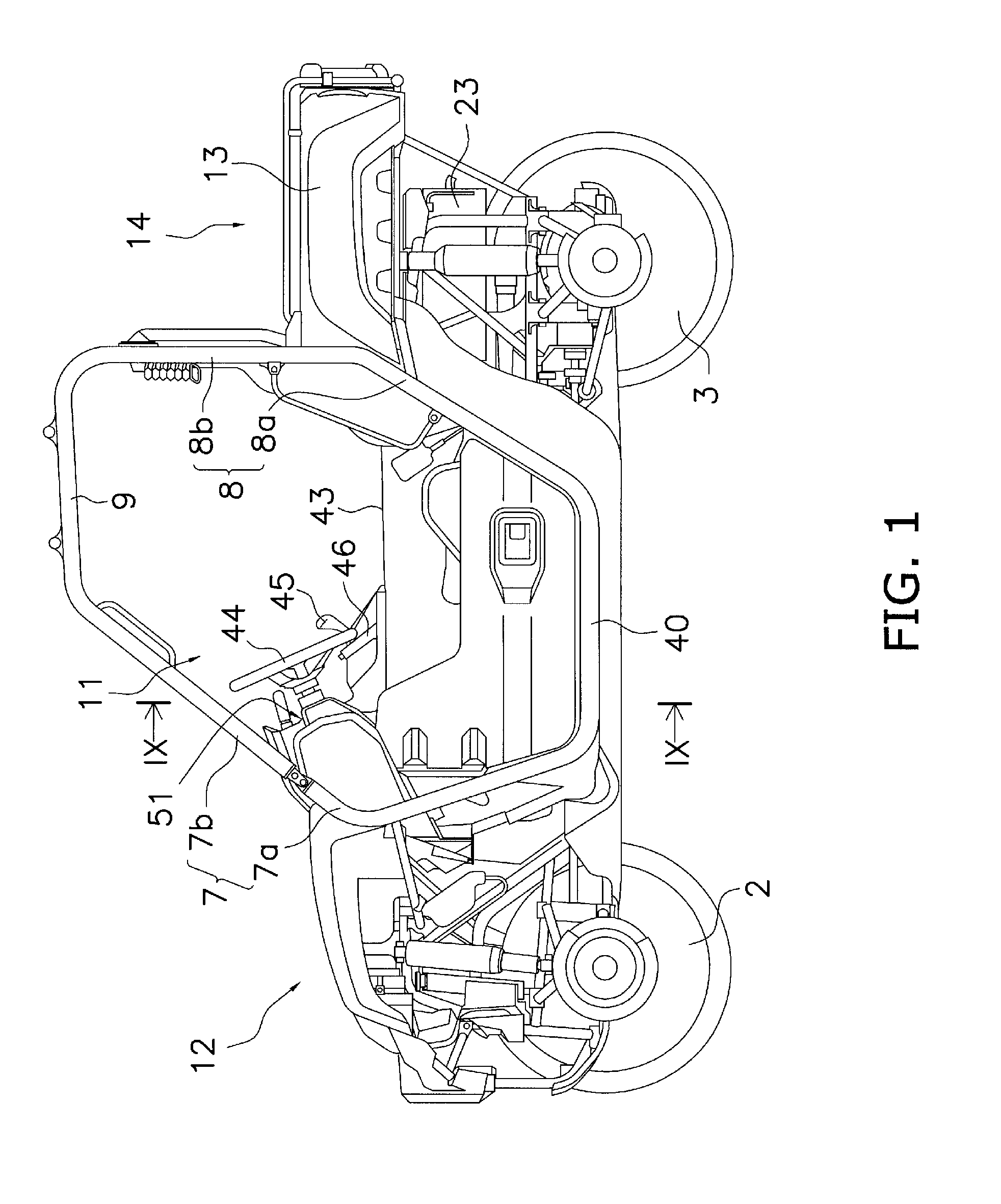
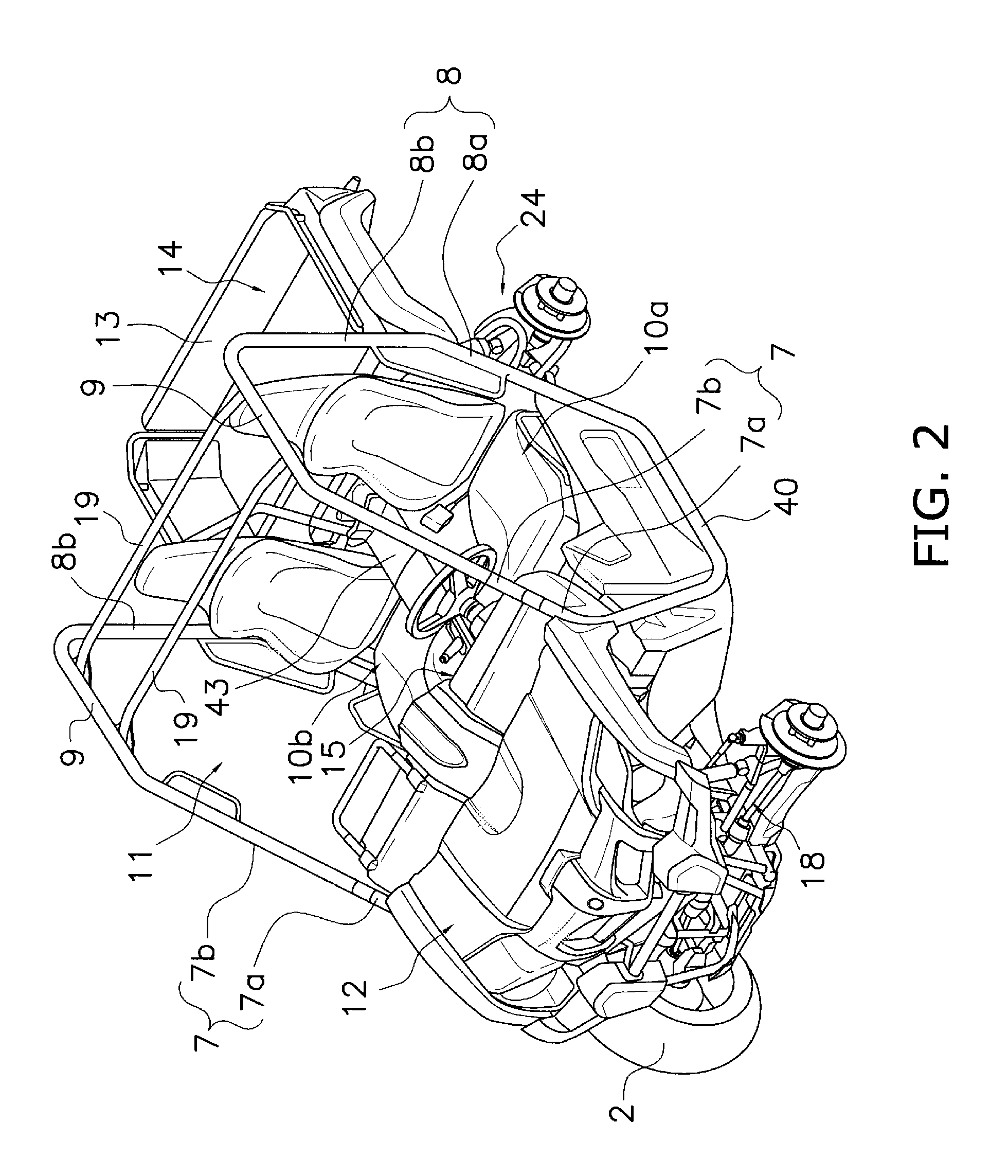
[0020]An all terrain vehicle according to preferred embodiments of the present invention will be hereinafter explained with reference to the attached figures. FIGS. 1 and 2 illustrate the all terrain vehicle that a left front wheel and a left rear wheel are removed. In the present specification, directional terms “front”, “rear”, “right” and “left” and their related terms mean directions seen in a condition that a driver and / or a passenger take a seat, excluding special occasions. Similarly, a term “longitudinal direction” means a front-to-rear direction of the vehicle in the condition that a driver and / or a passenger take a seat. On the other hand, a term transverse direction means a right-to-left direction of the vehicle in the condition that a driver and / or a passenger take a seat.

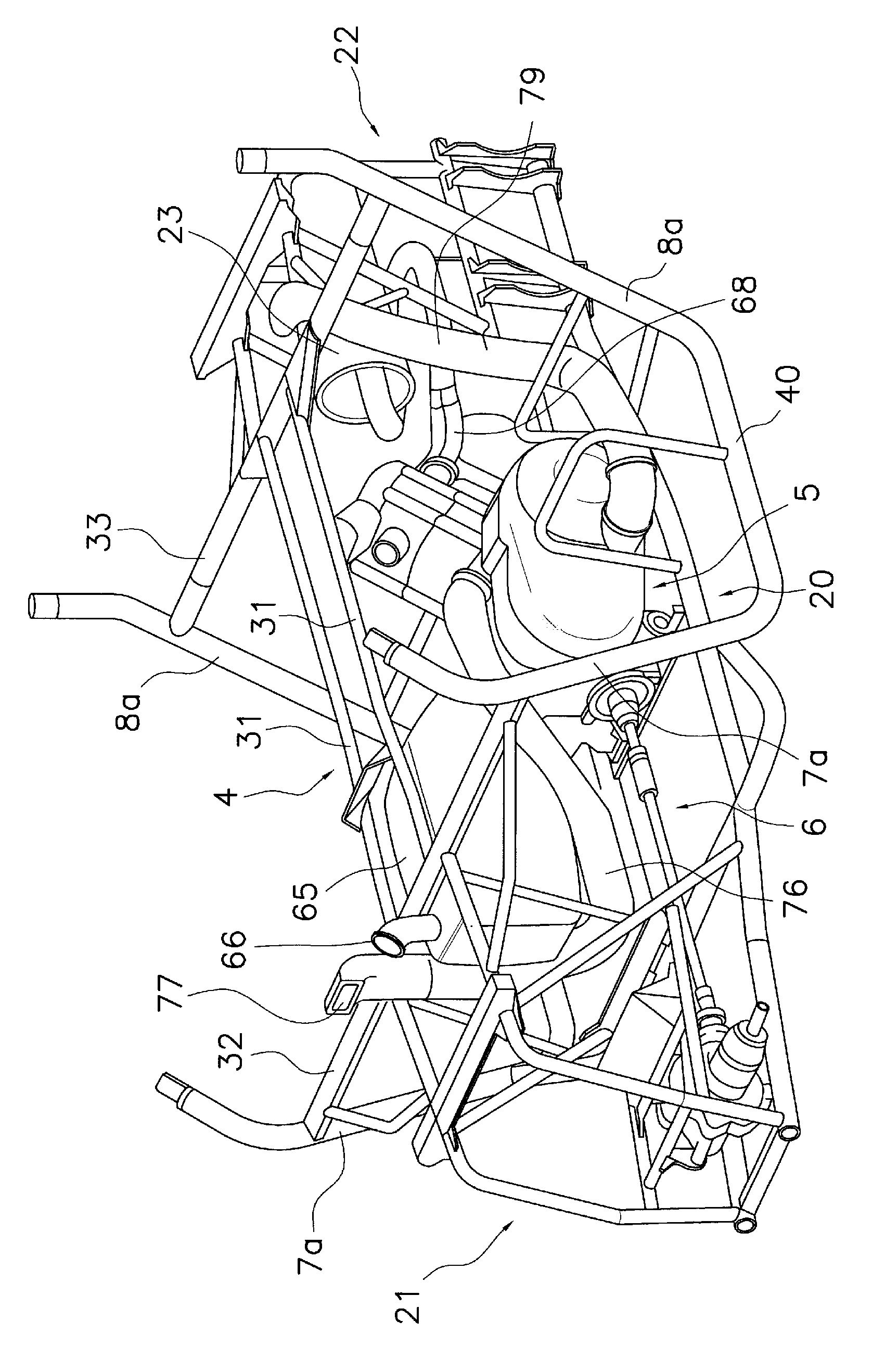
[0021]The all terrain vehicle, illustrated in FIGS. 1 to 6, includes a pair of right and left front wheels 2, a pair of right and left rear wheels 3, a vehicle body frame 4, an engine unit 5, a power tr...


PUM


Abstract

In an all terrain vehicle, a radiator is disposed forward of a front panel in a longitudinal direction of the vehicle. The radiator is also disposed in a transverse center of the vehicle. A fan is configured to blow air from the front to an area behind the radiator. An engine unit is disposed rearward of the front panel. A cargo bed is disposed rearward of a seat. An exhaust device is disposed under the cargo bed. The exhaust device is disposed in the transverse center of the vehicle. A communication path is positioned in the transverse center of the vehicle. The communication path connects a space positioned behind the radiator and a space that the exhaust device is disposed. The communication path at least partially overlaps with the fan in a front view of the vehicle.

Description

BACKGROUND OF THE INVENTION[0001]1. Field of the Invention[0002]The present invention relates to an all terrain vehicle.[0003]2. Description of the Related Art[0004]An all terrain vehicle is provided with a cabin in which a single seat or a plurality of seats and a floor are disposed. The floor is disposed forward of the single or plurality of seats. The floor is used for supporting the feet of a driver and / or a passenger thereon. Additionally, the cabin is sectioned apart from a vehicle body front portion through a front panel. The vehicle body front portion is disposed forward of the cabin, and the front panel stands upward from the floor. For example, US Patent Publication No. US2008 / 0289896 A1 discloses a conventional all terrain vehicle in which an engine unit is disposed rearward of the front panel. In the all terrain vehicle, an exhaust device is disposed rearward of the engine unit. It is difficult for the all terrain vehicle to enhance cooling of the engine unit and the exh...

Claims


Application Information

Patent Timeline
Patent Type & Authority Patents(United States)
IPC IPC(8): B60K13/00
CPCB60K11/04B60K5/04B60K13/02B62D21/183B60K17/34B60Y2200/20B60K13/04B60K2005/003
Inventor SUZUKI, YASUHIROHARA, MOTOYUKI
Owner YAMAHA MOTOR CO LTD
Why Eureka
Try Eureka