Electrical connector having thick film layers

a technology of electrical connectors and film layers, applied in the direction of couplings/cases, coupling devices, couplings for high frequency, etc., can solve the problems of reducing the space available for signal paths and undesirable signal reflections at certain frequencies

Active Publication Date: 2013-02-26
AMPHENOL CORP
View PDF103 Cites 111 Cited by
  • Summary
  • Abstract
  • Description
  • Claims
  • Application Information

AI Technical Summary

Benefits of technology

[0010]With those and other objects, advantages and features of the invention that may become hereinafter apparent, the nature of the invention may be more clearly understood by reference to the following detailed description of the invention, the appended claims and to the several drawings attached herein.

Problems solved by technology

One of the disadvantages of present electronic systems is the need, often times, to populate the surfaces of the interconnected printed circuit boards with passive circuit elements.
However, these passive circuit elements take up precious space on the board surface (thus reducing the space available for signal paths).
In addition, where these passive circuit elements on the board surface are connected to conductive vias, there could be undesirable signal reflections at certain frequencies due to impedance discontinuity and resonant stub effects.

Method used


Image

  • Electrical connector having thick film layers
  • Electrical connector having thick film layers
  • Electrical connector having thick film layers

Examples


Embodiment Construction

[0041]Several preferred embodiments of the invention are described for illustrative purposes, it being understood that the invention may be embodied in other forms not specifically shown in the drawings.

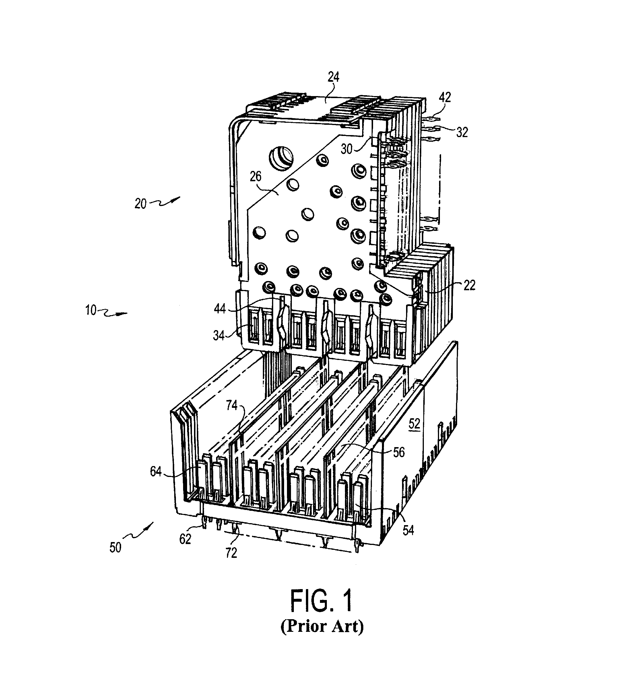
[0042]FIG. 1 shows a perspective view of a prior art electrical connector assembly 10 illustrated as FIG. 1 in U.S. Pat. No. 6,409,543. The '543 patent, which is directed to the GbX® connector, is assigned to the assignee of the present invention and is incorporated by reference herein. The electrical connector assembly 10 includes a daughtercard connector 20 that is connectable to a first printed circuit board (not shown) and a backplane connector 50 that is connectable to a second printed circuit board (not shown). The daughtercard connector 20 has a plurality of modules or wafers 22 which are preferably held together by a stiffener 24.

[0043]Each wafer 22 includes a plurality of signal conductors 30, a shield plate (not visible in FIG. 1), and a dielectric housing 26 that is formed...


PUM

PropertyMeasurementUnit
frequencyaaaaaaaaaa
lengthaaaaaaaaaa
widthaaaaaaaaaa

Abstract

An electrical connector electrically connects a first printed circuit board and a second printed circuit board, where the electrical connector includes: (a) an insulative housing; (b) a plurality of signal conductors, with at least a portion of each of the plurality of signal conductors disposed within the insulative housing; (c) each of the plurality of signal conductors having a first contact end, a second contact end and an intermediate portion therebetween; and (d) a passive circuit element electrically connected to the intermediate portion of each of the plurality of signal conductors, where the passive circuit element is housed in an insulative package and includes at least a capacitor or an inductor.

Description

RELATED APPLICATIONS[0001]This application is a continuation-in-part of Ser. No. 12 / 784,914, filed May 21, 2010, and claims the benefit of provisional application No. 61 / 367,291, filed Jul. 23, 2010, and provisional application No. 61 / 386,782, filed Sep. 27, 2010, the contents of which are incorporated herein by reference.BACKGROUND OF THE INVENTION[0002]This invention relates generally to an electrical connector incorporating passive circuit elements and methods of manufacturing such an electrical connector.[0003]Modern electronic circuitry is often built on printed circuit boards. The printed circuit boards are then interconnected to create an electronic system, such as a server or a router for a communications network. Electrical connectors are generally used to make these interconnections between the printed circuit boards. Typically, connectors are made of two pieces, with one piece on one printed circuit board and the other piece on another printed circuit board. The two piece...

Claims


Application Information

Patent Timeline
Patent Type & Authority Patents(United States)
IPC IPC(8): H01R13/66
CPCH01R12/724H01R13/6473H01R43/24H01R13/46H01R13/6597H01R13/6616Y10T29/49224H01R13/6633H01R13/719H01R13/6625
Inventor KHILCHENKO, LEONGAILUS, MARK W.
Owner AMPHENOL CORP
Why Eureka
Try Eureka