System for decontaminating industrial output gases

a technology of industrial output and gaseous output, which is applied in the direction of filter regeneration, dispersed particle filtration, and liquid separation agent, etc., can solve the problems of excessive steam production and difficulty in producing a system capable of decontaminating both particulate and gaseous output of various industrial facilities

Inactive Publication Date: 2013-02-26
ALSAFFAR ABDULREIDHA A T A
View PDF27 Cites 18 Cited by
  • Summary
  • Abstract
  • Description
  • Claims
  • Application Information

AI Technical Summary

Benefits of technology

[0010]Yet another embodiment is adapted for processing the steam byproduct produced from so-called “clean” industrial processes, e.g., due to the cooling needs of nuclear power plants. As there are no particulates in such output, this embodiment deletes the filter apparatus and substitutes a cooling system for the steam output. This can be quite valuable in arid areas where the steam may be recaptured as useful water, e.g., for recirculation through the cooling system of the plant, rather than being released into the atmosphere.
[0011]These and other features of the present invention will become readily apparent upon further review of the following specification and drawings.

Problems solved by technology

Even operations that produce relatively “clean” atmospheric emissions will often produce excessive amounts of steam as a byproduct of their cooling needs.
As a result, it has proven difficult to produce a system that is capable of decontaminating both particulate and gaseous output from various industrial facilities.

Method used


Image

  • System for decontaminating industrial output gases
  • System for decontaminating industrial output gases
  • System for decontaminating industrial output gases

Examples


Embodiment Construction

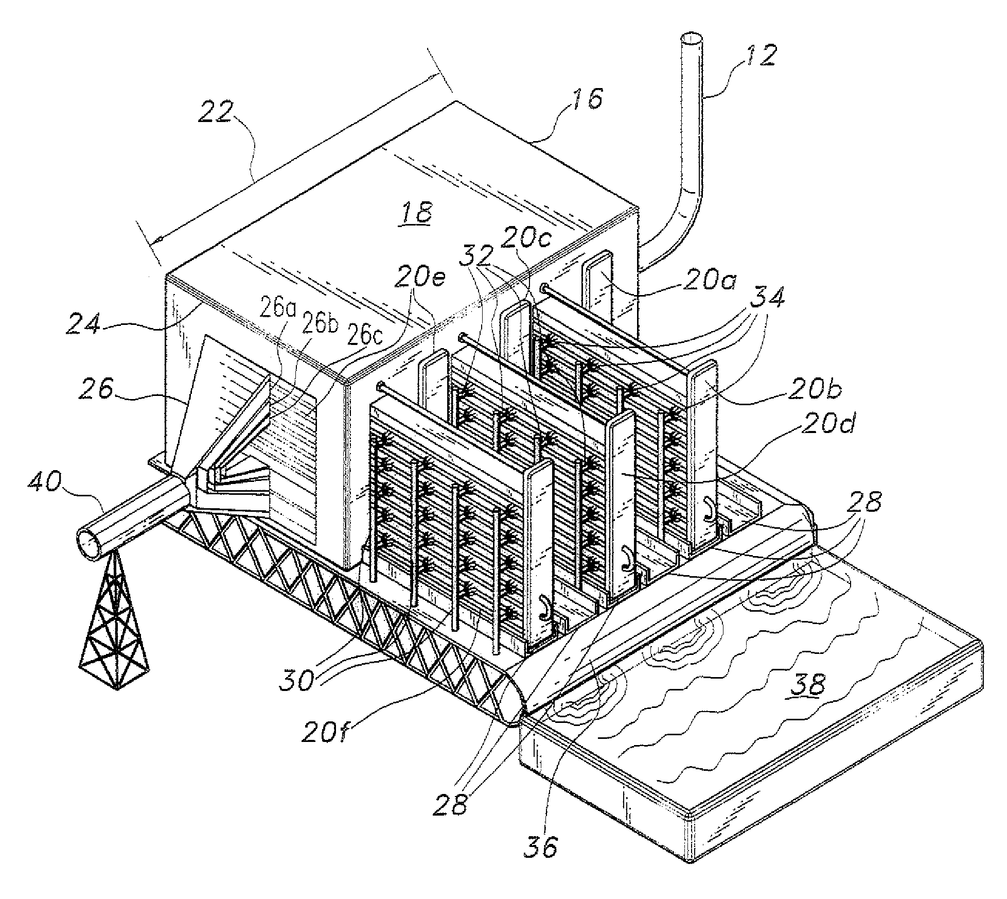
[0018]The system for decontaminating industrial output gases includes several major subsystems for removing particulates from various gases and for classifying or separating the remaining gases into their separate elements or compounds, as appropriate. The system may include a subsystem for burning off remaining combustible gases and recycling the resulting products.

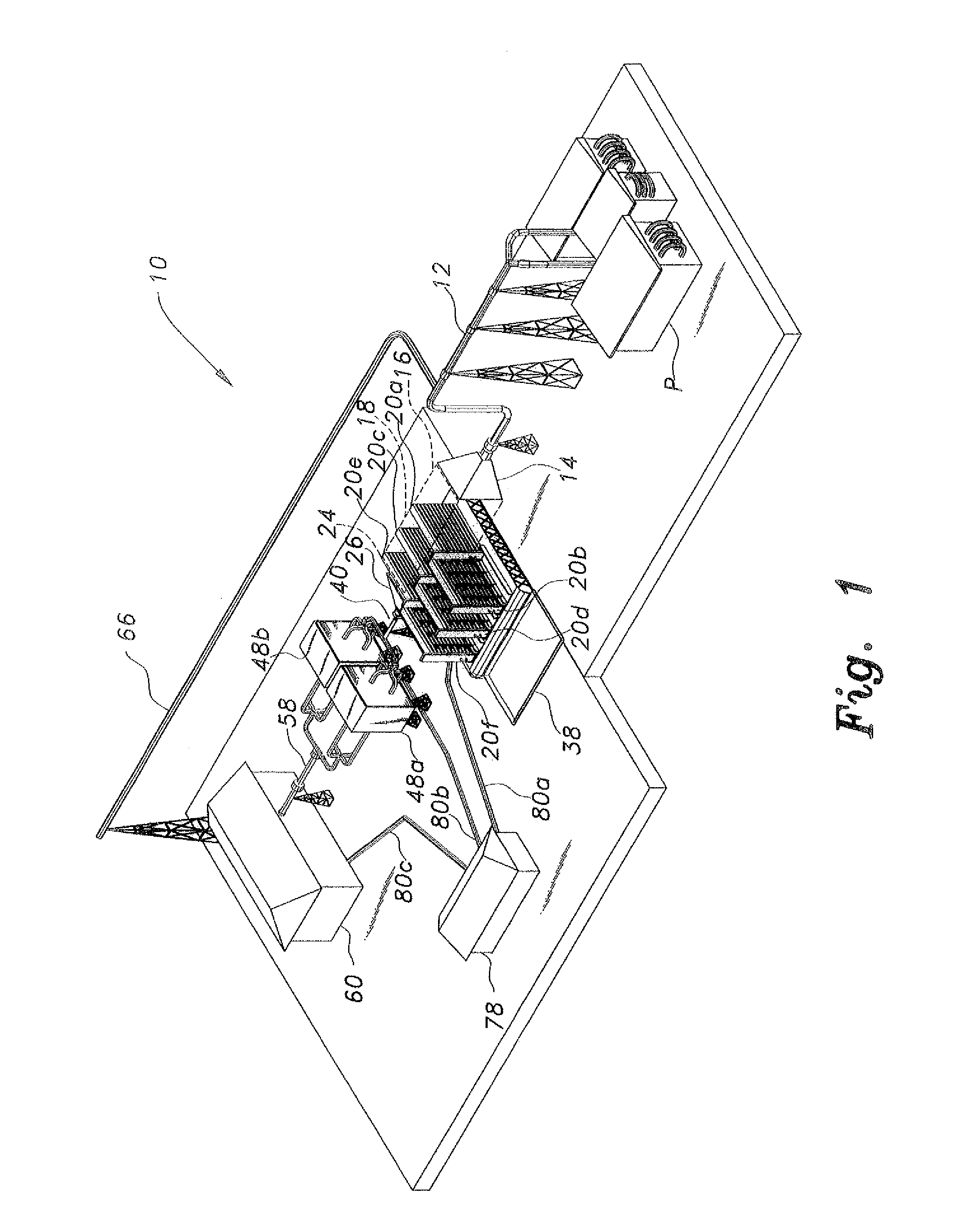
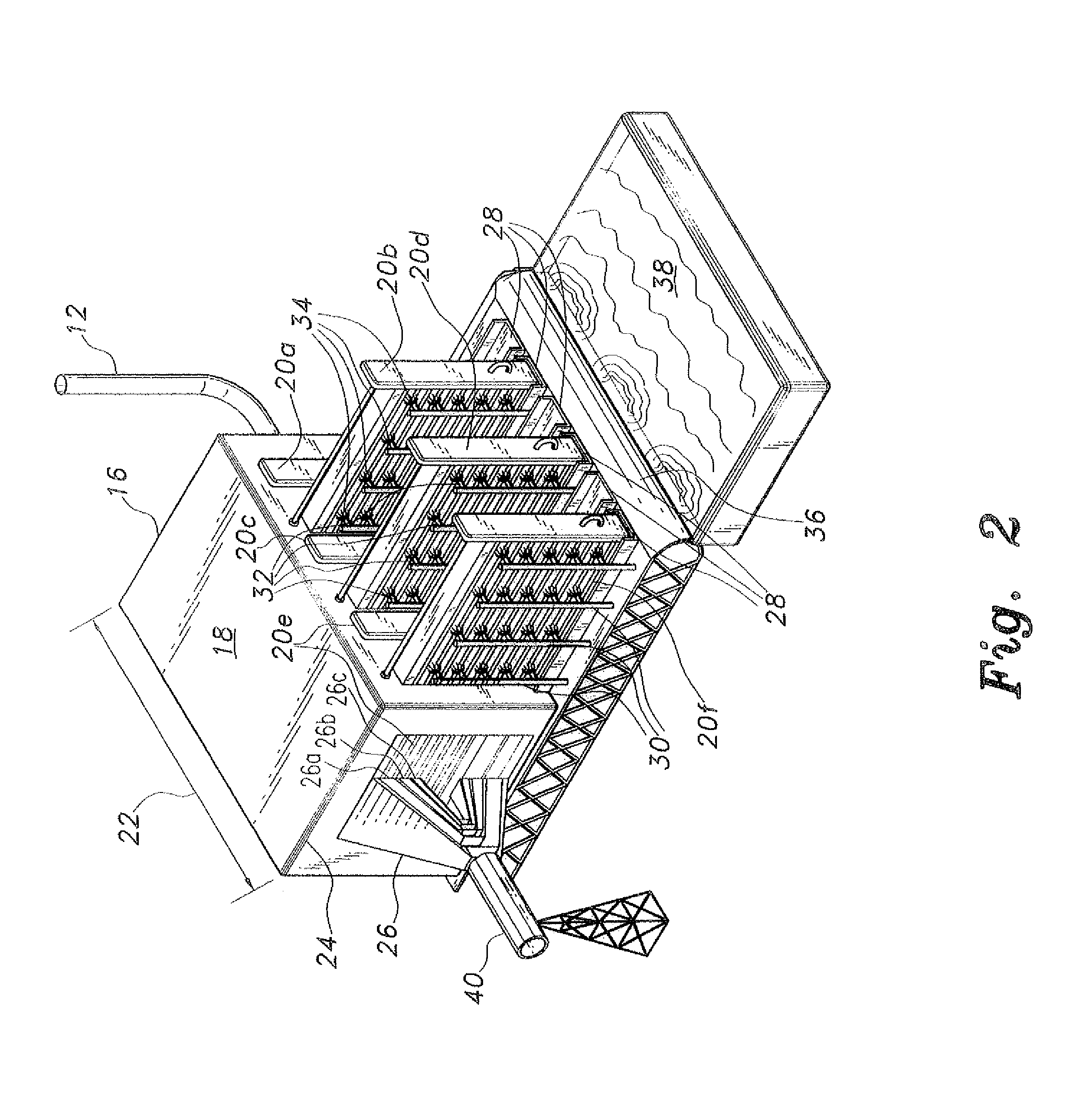
[0019]FIG. 1 of the drawings provides a general perspective view of all of the subsystems incorporated into a first embodiment of the system for decontaminating industrial output gases, generally designated as system 10. Gases produced by an industrial factory or plant P are delivered to the system 10 by a gas input flue 12 to a filter input plenum 14 at the upstream or inlet end 16 of a filter housing 18, shown in broken lines in FIG. 1 in order to show a first plurality of filters 20a, 20c, and 20e therein. Alternatively, the system 10 may be located closer to the factory or plant P, and the gas input flue 12 may be sh...


PUM

PropertyMeasurementUnit
lengthaaaaaaaaaa
chemical compositionsaaaaaaaaaa
temperaturesaaaaaaaaaa

Abstract

The system for decontaminating industrial output gases may process both particulate and gaseous emissions from industrial facilities. The system may be located with or adjacent to an industrial facility or at some distance from the facility. In one embodiment the system includes a subsystem of alternating active and inactive filters, and a wash subsystem cleaning the inactive filters during the cycle. The wash water is captured in a basin for further processing of the chemical particulates therein. Fans located downstream of the filters draw the gaseous industrial output through the filters. Remaining vapor passes to a classification plant where the gases are separated into their constituent elements or compounds. Gases that to are allowed to escape may be burned, and the resulting gases recirculated through the system. Another embodiment is adapted for processing steam, and cools the steam for use as liquid water, rather than allowing it to escape as vapor.

Description

CROSS-REFERENCE TO RELATED APPLICATIONS[0001]This is a continuation of my prior application Ser. No. 13 / 232,713, filed Sep. 14, 2011 now pending.BACKGROUND OF THE INVENTION[0002]1. Field of the Invention[0003]The present invention relates generally to atmospheric emissions and pollution control systems, and particularly to a system for decontaminating industrial output gases produced by a factory or other industrial plant or the like.[0004]2. Description of the Related Art[0005]Factories and other industrial centers and operations typically produce various gaseous emissions as byproducts of their processes. As time has progressed it has become widely recognized that many, if not most, of these gases are harmful to the environment, and regulations have been implemented to require that such output be minimized or at least controlled.[0006]As factories and industrial operations produce a wide variety of goods, the chemical compositions of their emissions vary widely as well. Nonetheles...

Claims


Application Information

Patent Timeline
Patent Type & Authority Patents(United States)
IPC IPC(8): B01D46/00
CPCB01D46/0058B01D46/0082B01D2279/40B01D46/90B01D46/79
Inventor ALSAFFAR, ABDULREIDHA A. T. A.
Owner ALSAFFAR ABDULREIDHA A T A
Why Eureka
Try Eureka