Slide locking mechanism for seat

a technology of sliding mechanism and seat, which is applied in the direction of mechanical control devices, roofs, instruments, etc., can solve the problems of increased cost, increased structural complexity and cost, and the seat cannot be fixed, so as to reduce the play and structure simple

Inactive Publication Date: 2013-03-05
DELTA KOGYO CO LTD
View PDF12 Cites 12 Cited by
  • Summary
  • Abstract
  • Description
  • Claims
  • Application Information

AI Technical Summary

Benefits of technology

[0011]It is an object of the present invention to provide a slide locking mechanism for a seat, which is capable of reducing a play between a locking member and a corresponding one of a plurality of latch portions in a locked state, with a simple structure.
[0012]It is another object of the present invention to provide a slide locking mechanism for a seat, which is less likely to cause a force to concentrate on the locking member and the corresponding latch portion.

Problems solved by technology

However, when the seated person moves the seat to a target position in the frontward-rearward direction, the slide locking mechanism is likely to fall into an undesirable situation where the locking member is not aligned with any one of the latch portions, so that the locking member is brought into contact with a portion between adjacent ones of the latch portions and precluded from being inserted into the hole of any one of the latch portions.
However, this approach leads to the occurrence of a play (free gap in the longitudinal direction) between the inserted locking member and the corresponding latch portion, which causes a wobbling movement of the seat in the locked state to preclude the seat from being fixed.
However, in the locking mechanism disclosed in the JP 10-500647A, it is necessary to provide the rotation means to each of the locking bolts in order to rotate the locking bolt about the axis, which leads to structural complexity and an increase in cost.
Therefore, in order to prevent fracture of the inserted locking bolt and damage in the front or rear inner wall region of the corresponding latch portion in such a situation, strength of each of the locking bolts and the lower rail has to be increased, which causes a problem of an increase in cost.

Method used


Image

  • Slide locking mechanism for seat
  • Slide locking mechanism for seat
  • Slide locking mechanism for seat

Examples


Embodiment Construction

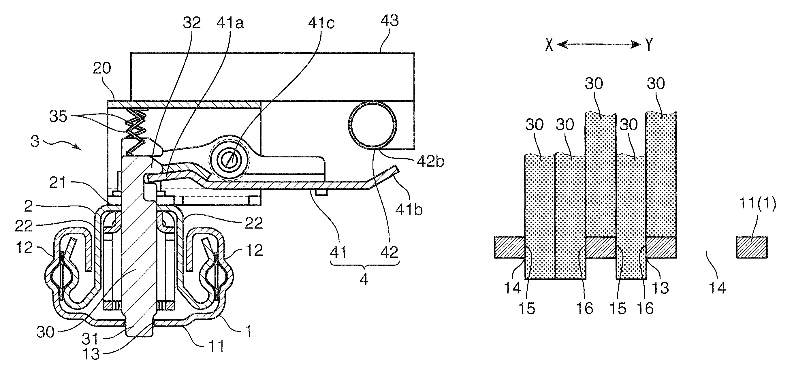
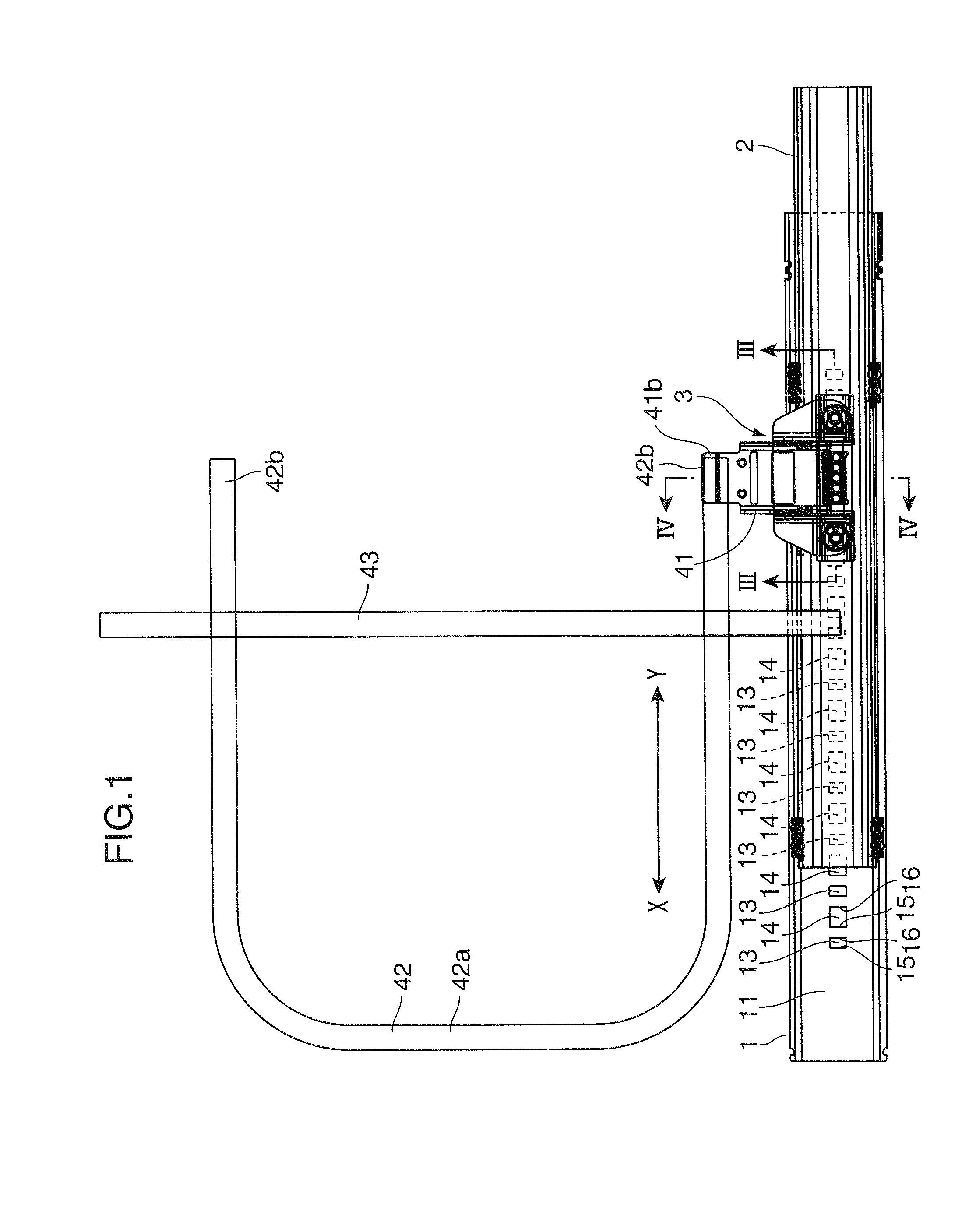
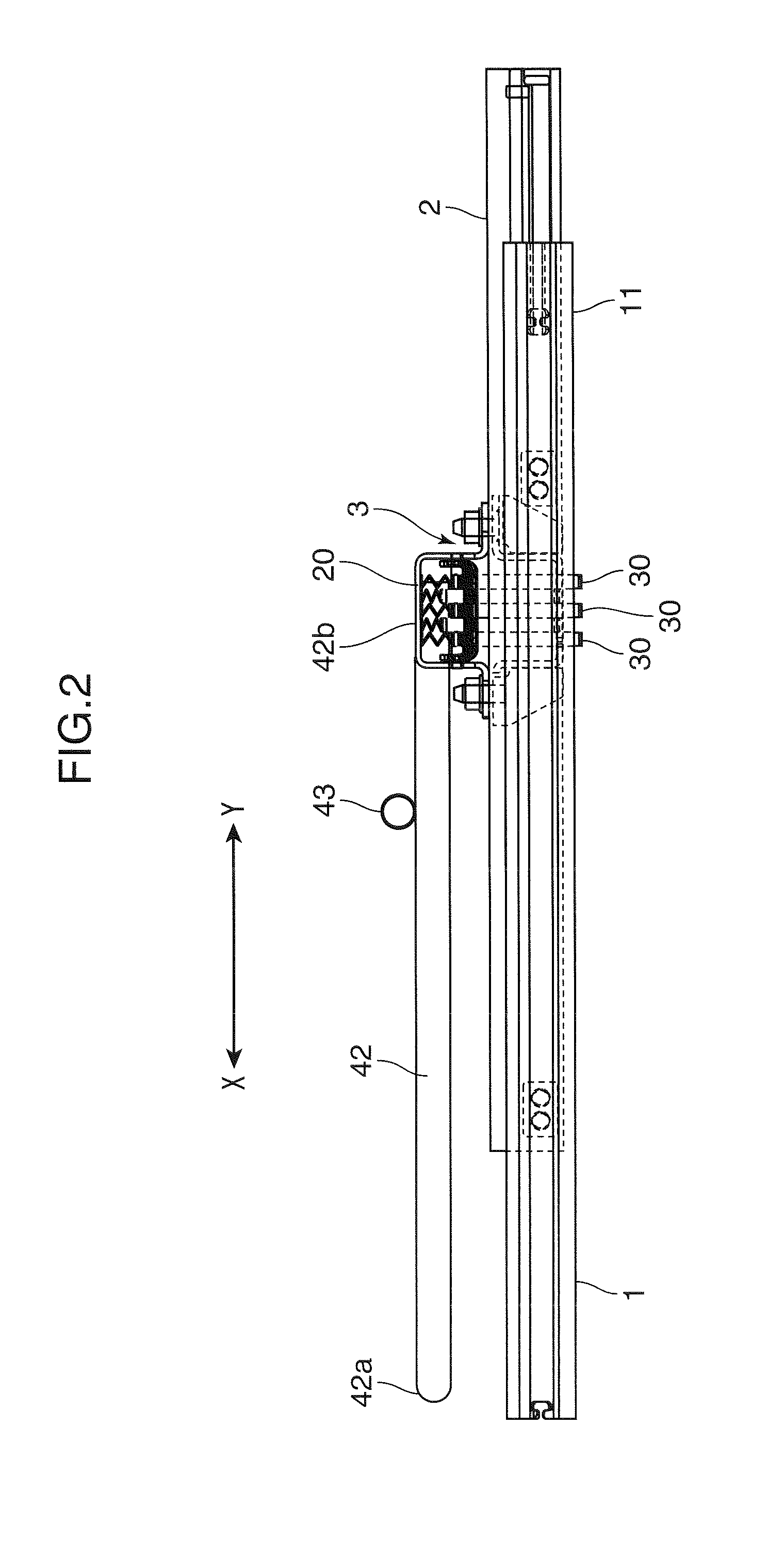
[0032]With reference to the drawings, the present invention will now be specifically described based on an embodiment thereof. FIG. 1 is a schematic top plan view showing a seat sliding apparatus for an automobile, which has a slide locking mechanism according to one embodiment of the present invention. FIG. 2 is a side view of the seat sliding apparatus in FIG. 1. FIG. 3 is an enlarged sectional view taken along the line III-III in FIG. 1. FIG. 4 is an enlarged sectional view taken along the line IV-IV in FIG. 1.

[0033]As shown in FIGS. 1 and 2, the automobile seat sliding apparatus in this embodiment comprises a lower rail 1, an upper rail 2, and a slide locking mechanism 3.

[0034]The lower rail 1 is an elongate-shape member. As shown in FIG. 4, the lower rail 1 has a bottom wall 11, and two right and left lateral walls 12, 12 formed to extend bendingly and upwardly from respective widthwisely opposite ends of the bottom wall 11. As shown in FIG. 1, the bottom wall 11 has a pluralit...


PUM


Abstract

Disclosed is a slide locking mechanism for a seat, which comprises at least five locking pieces, a plurality of first latch portions and a plurality of second latch portions. An opening width of a hole of each of the first latch portions in a longitudinal direction of a lower rail is equal to a width of each of the locking pieces in the longitudinal direction, and an opening width of a hole of each of the second latch portions in the longitudinal direction is greater than the opening width of each of the holes of the first latch portions. The first latch portions and the second latch portions are alternately arranged along the longitudinal direction.

Description

BACKGROUND OF THE INVENTION[0001]1. Field of the Invention[0002]The present invention relates to a slide locking mechanism for a seat.[0003]2. Description of the Related Art[0004]Heretofore, there has been known a slide locking mechanism for a seat, such as an automobile seat. For example, the conventional slide locking mechanism has a locking member held by an upper rail which is fixed to a seat in such a manner that a longitudinal direction of the upper rail is oriented along a frontward-rearward direction of an automobile body. Further, the slide locking mechanism has a plurality of latch portions having the same configurations, the latch portions are provided in a bottom wall of a lower rail fixed to the automobile body, and arranged in one line along the longitudinal direction. Each of the latch portions has a hole formed to allow the locking member to be releasably inserted thereinto. The locking member is formed such that a width thereof in the longitudinal direction is equal...

Claims


Application Information

Patent Timeline
Patent Type & Authority Patents(United States)
IPC IPC(8): F16M13/00
CPCB60N2/0806Y10T74/20636
Inventor TARUSAWA, MAKOTODOMOTO, YASUHITOWAKAYAMA, HIROYUKI
Owner DELTA KOGYO CO LTD
Why Eureka
Try Eureka