Ophthalmologic biometric or image generating system and method for detection and evaluation of measured data

a biometric or image-generating system and measurement data technology, applied in the field of ophthalmological biometric or image-generating system and method for detection and analysis of measurement data, can solve the problems of limited to a defined deflection pattern in a defined direction, loud and expensive, and other patterns that cannot be realized with slower and more elaborate non-resonant galvanometer scanners, etc., to achieve less elaborate and more cost-effective effects

Active Publication Date: 2013-03-05
CARL ZEISS MEDITEC AG
View PDF36 Cites 11 Cited by
  • Summary
  • Abstract
  • Description
  • Claims
  • Application Information

AI Technical Summary

Benefits of technology

[0027]The invention herein is based on the task of realizing a system for deflection of measurement beams for ophthalmological biometric or image-producing systems, whereby the known disadvantages from prior art are remedied and which is significantly more cost-effective and less elaborate.
[0028]Furthermore, it should allow for the recording of undistorted tomograms and accurate biometric data.

Problems solved by technology

However, due to the increasing complexity and desired individualization of the implants, measurement data of more than one depth profile (A-scan) of the eye, particularly of several laterally offset A-scans, are required.
This is a contradiction with conventional galvanometer scanners since the resonant variations may be able to scan very quickly but are very often limited to sine-like scan patterns.
However, other patterns can only be realized with slower and more elaborate non-resonant galvanometer scanners.
Said great challenges to the deflection equipment regarding speed, control accuracy, and linearity are, e.g., further enhanced when so-called tracking systems, already widely used in ophthalmology, are used which detect, register and / or actively compensate the eye movements during the course of the measurements.
Polygon mirrors are able to scan very quickly and stably but are limited to a defined deflection pattern in a defined direction.
Additionally, they are very loud and expensive.
In principle, deformable mirrors and liquid crystal modulators for beam deflection are also suitable but in general slow by comparison.
The solutions for deflection systems for scanning measurement value logging, which are known in accordance with prior art and described herein, have the disadvantage of being very elaborate and expensive.

Method used


Image

  • Ophthalmologic biometric or image generating system and method for detection and evaluation of measured data
  • Ophthalmologic biometric or image generating system and method for detection and evaluation of measured data
  • Ophthalmologic biometric or image generating system and method for detection and evaluation of measured data

Examples


Embodiment Construction

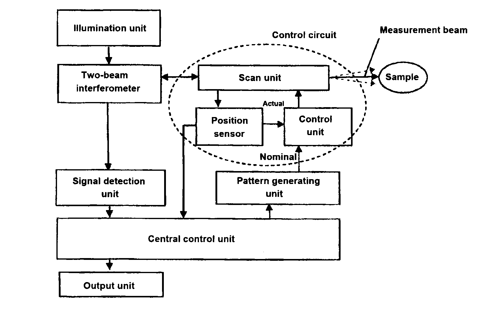
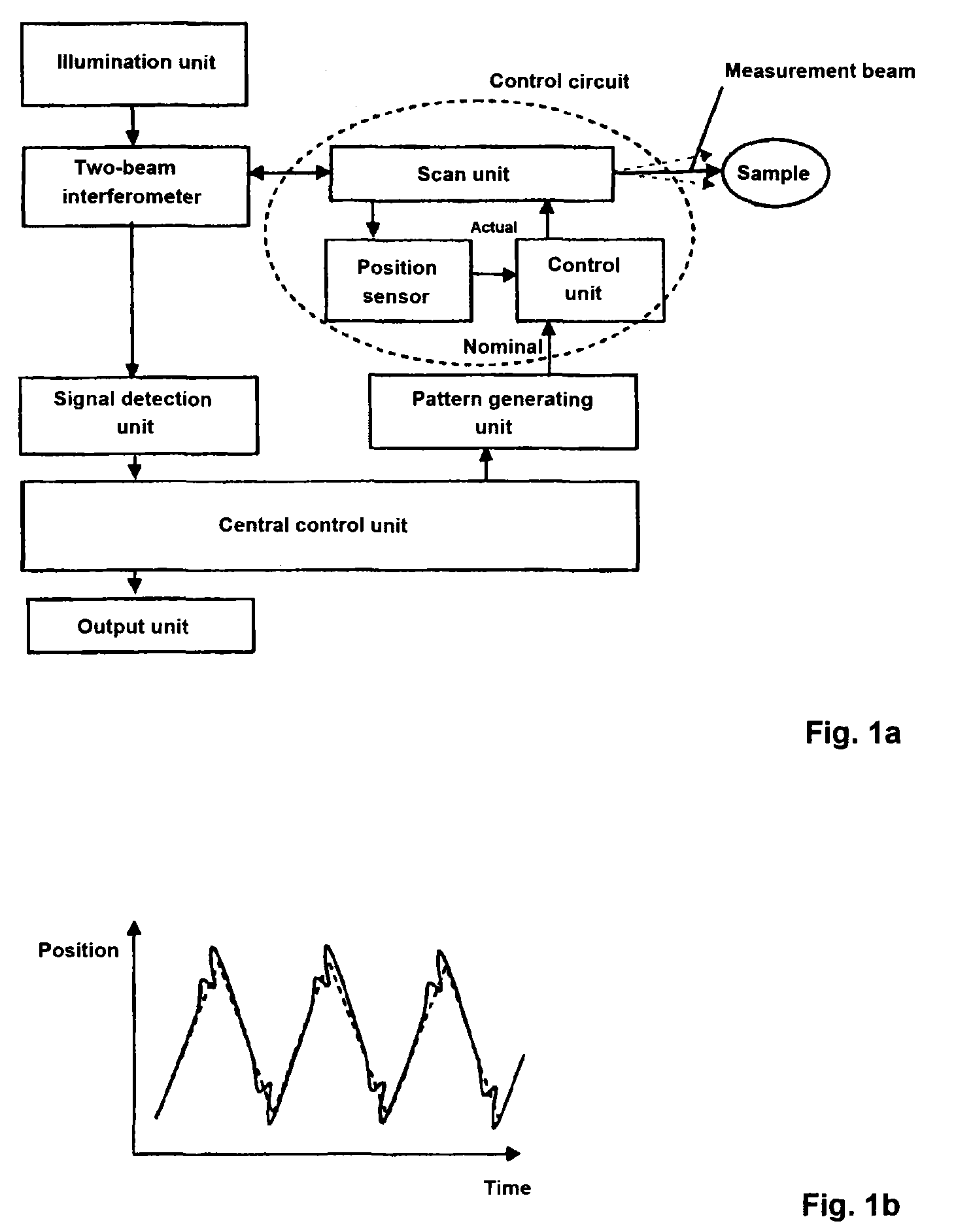
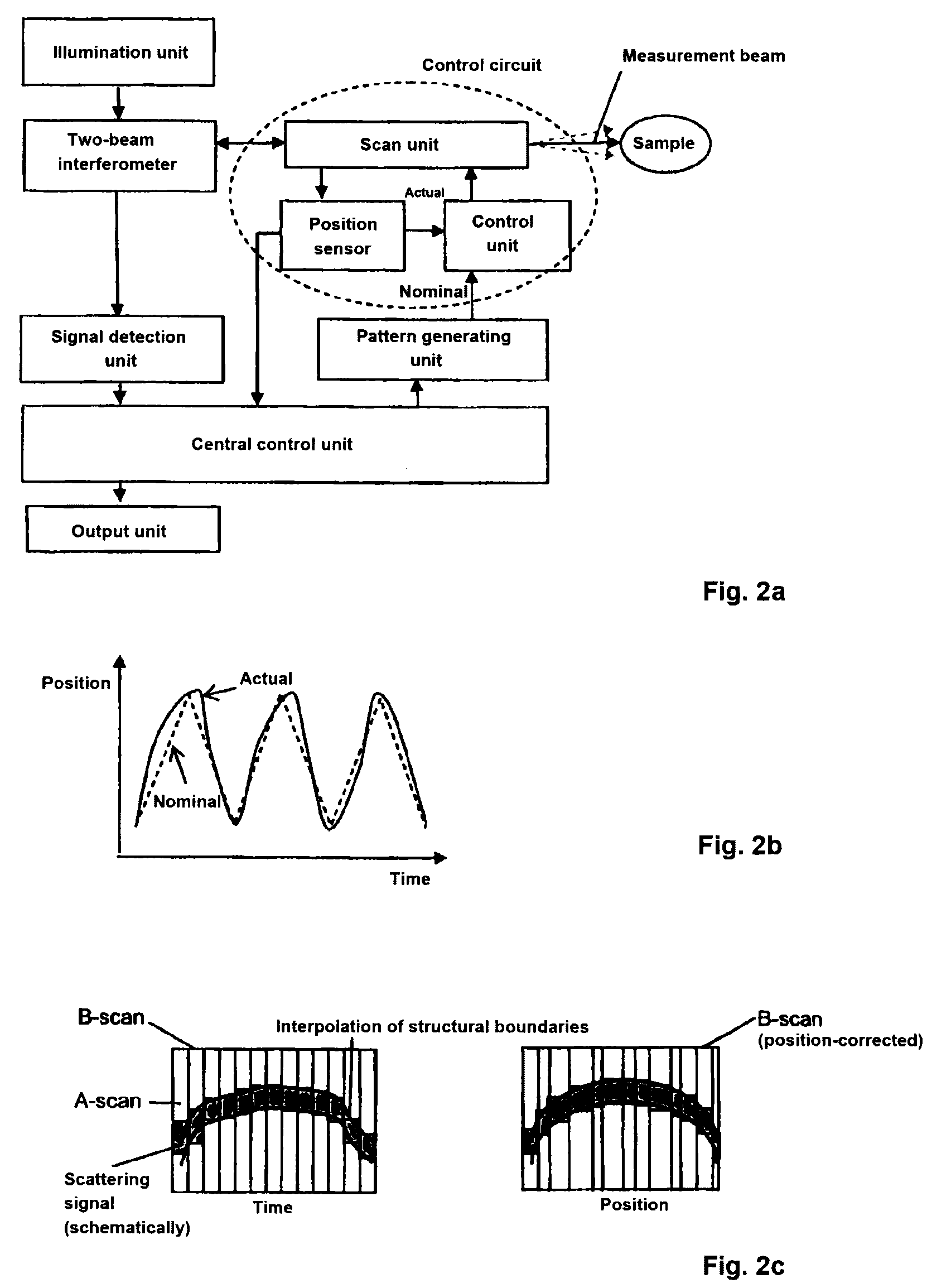
[0045]A ophthalmological biometric or image-producing system, according to an example embodiment of the invention, is based on an interferometric measurement arrangement, which includes an illumination unit, a two-beam interferometer, such as a Michelson or Mach-Zehnder interferometer, a signal detection as well as a central control unit with output unit, and which includes a pattern generating unit for the optical scan unit, which is activated via the central control unit. The pattern generating unit includes an optical scan unit, a control unit for controlling the deflection of at least one measurement beam with regard to the eye structure as well as a position sensor for measuring the realized deflections of the optical scan unit, whereby the control unit, optical scan unit, and position sensor can form a control circuit or control loop.

[0046]Thereby, the pattern generating unit can, for example be a memory unit, which contains a value table, the values of which are read incremen...


PUM


Abstract

An ophthalmological biometric or image-producing system and method for detection and analysis of measurement data including a measurement arrangement with an illumination unit for illuminating the eye with at least one measurement beam, a signal detection unit for the detection of the light portions scattered or reflected back from the eye, a central control unit with an output unit, and a pattern generating unit which includes an optical scan unit, a control unit as well as a position sensor for measuring the realized deflections of the optical scan unit, whereby control unit, optical scan unit and position sensor can form a control circuit. Thereby, the position sensor, except for the connection within the possible control circuit, includes a connection to a unit of the measurement arrangement for optimizing measurement value logging or to the central control unit for correcting the biometric measurements or tomograms.

Description

[0001]This application claims priority to German Patent Application No. 10 2009 041 996.9 filed on Sep. 18, 2009, said application is incorporated herein by reference in it's entirety.FIELD OF THE INVENTION[0002]The invention relates to an ophthalmological biometric or image-producing system and method for detection and analysis of measurement data, for determining sizes, distances and / or geometric relations of eye structures.BACKGROUND[0003]These measurements are necessary, for example, for the adjustment of implants, such as intraocular lenses after cataract surgery.[0004]However, due to the increasing complexity and desired individualization of the implants, measurement data of more than one depth profile (A-scan) of the eye, particularly of several laterally offset A-scans, are required.[0005]Other ophthalmological devices serve primarily for producing and evaluating two-dimensional images, sectional images, and volume scans of various areas of the eye with regard to the visual ...

Claims


Application Information

Patent Timeline
Patent Type & Authority Patents(United States)
IPC IPC(8): A61B3/10A61B3/14A61B3/00
CPCA61B3/102
Inventor HACKER, MARTINPABST, THOMASEBERSBACH, RALFANTKOWIAK, GERARDBISSMANN, WILFRIEDREICH, MATTHIAS
Owner CARL ZEISS MEDITEC AG
Why Eureka
Try Eureka