Image forming apparatus of efficiently storing information relating to client apparatuses in network environment

a network environment and information storage technology, applied in the field of image forming apparatus, can solve the problems of reducing the cost of an image forming apparatus, and different operations from the intended ones, and achieve the effect of efficient storage of information relating

Active Publication Date: 2013-03-05
KONICA MINOLTA BUSINESS TECH INC
View PDF13 Cites 5 Cited by
  • Summary
  • Abstract
  • Description
  • Claims
  • Application Information

AI Technical Summary

Benefits of technology

[0011]The present invention is contrived in view of the above problems, and an object of the present invention is to provide an image forming apparatus, which is used in a network environment including a plurality of image forming apparatuses and a plurality of client apparatus, capable of efficiently storing information relating to the client apparatuses, a data transfer system including such an image forming apparatus, and an information management method for such an apparatus and a system.
[0017]The image forming apparatus and the data transfer system including the image forming apparatus according to the present invention, even when a storage capacity of each image forming apparatus is smaller than a capacity required for storing information relating to all of the client apparatuses that are connected to the data transfer system, information relating to the connected client apparatuses can be efficiently stored in the data transfer system as a whole.

Problems solved by technology

This disadvantageously hinders cost reduction of an image forming apparatus.
Accordingly, when an amount of information relating to the client apparatuses that is stored reaches the maximum amount of memory of an image forming apparatus having a capacity that is the largest among that of the image forming apparatuses connected to the network, a problem occurs that, even if the network includes a plurality of image forming apparatuses and a total amount of memory for the network as a whole is large, a client apparatus that is connected to the network over the number corresponding to the amount of memory of the image forming apparatus having the largest capacity cannot exchange data with any of the image forming apparatuses.
This, as a result, makes an operating procedure complex and can results in a faulty operation, disadvantageously causing an operation different from an intended one.

Method used


Image

  • Image forming apparatus of efficiently storing information relating to client apparatuses in network environment
  • Image forming apparatus of efficiently storing information relating to client apparatuses in network environment
  • Image forming apparatus of efficiently storing information relating to client apparatuses in network environment

Examples


first embodiment

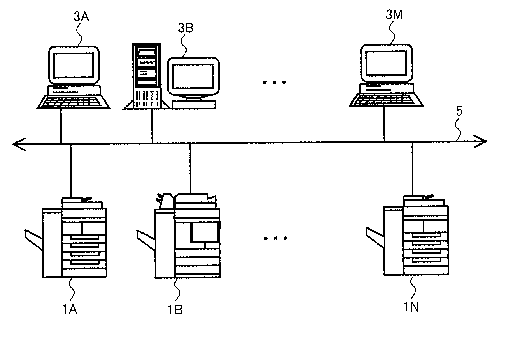
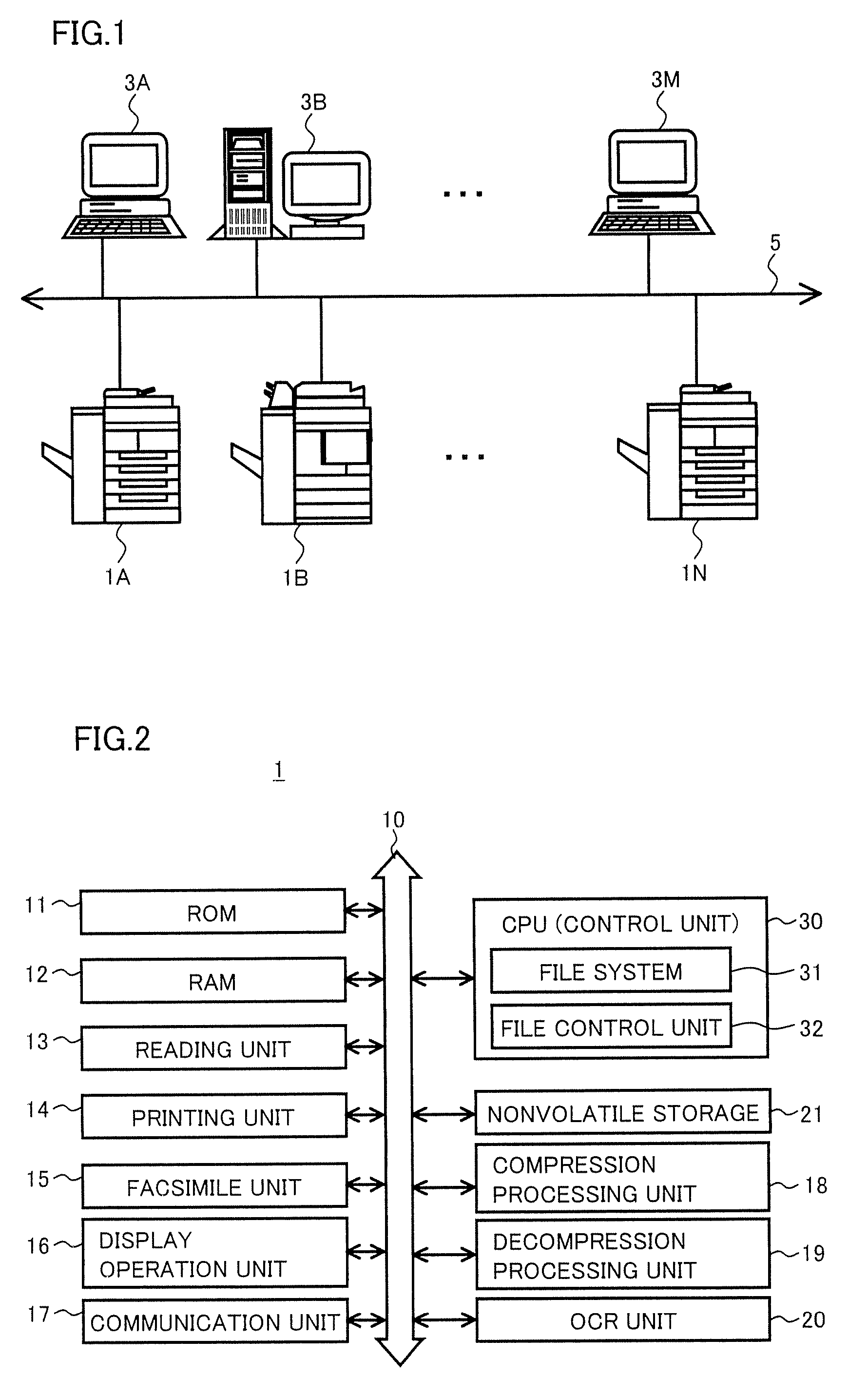
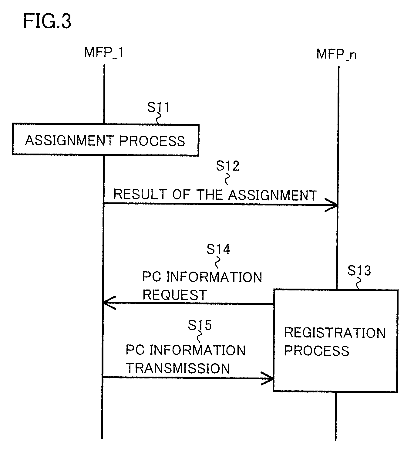
[0043]FIG. 3 is a diagram schematically illustrating a processing flow between the representing MFP and the MFPs other than the representing MFP in the data transfer system according to a first embodiment. In FIG. 3, the representing MFP is represented by an MFP_1, and the MFPs other than the representing MFP are represented by an MFP_n. MFP_n that represents the MFPs other than the representing MFP includes MFP_1 when functioning as the other MFP.

[0044]Referring to FIG. 3, MFP_1 as the representing MFP carries out an assignment process in step S11. With this process, each of the MFPs included in the data transfer system is assigned with the PCs that are connectable to the MFP. Then, in step S12, the result of the assignment is transferred to each MFP_n. In response to this result, in step S13, MFP_n carries out a registration process of registering an assigned PC as a PC that is connectable to this MFP_n. At this time, if the result of the assigned PC includes PC information for a ...

second embodiment

[0065]FIG. 10 is a diagram schematically illustrating a processing flow between the representing MFP and the MFPs other than the representing MFP in the data transfer system according to a second embodiment. In FIG. 10, the representing MFP is represented by MFP_1, and the MFPs other than the representing MFP are represented by MFP_n. MFP_n as the MFPs other than the representing MFP includes MFP_1 when functioning as the other MFP.

[0066]Referring to FIG. 10, in step S21, MFP_n as the MFPs other than the representing MFP carries out a history construction process, and constructs history information for the data transfer. As used herein, “history information” refers to an access count of each PC, which has transmitted an instruction for the data transfer, to the MFPs. Alternatively, “history information” can refer to, for each function used for the data transfer, an access count of the MFP to the function each PC, which has transmitted an instruction for the data transfer using the f...

modified example

[0083]The above described is the example in which, for each PC, the history information of the MFPs to which the PC has connected is accumulated, and the assignment of the PCs is carried out based on the history information. Similarly, it is possible to carry out the assignment for each user based on the history information, by accumulating the history information with which the data transfer has been carried out. Assumption is given that a user logs in when using an apparatus connected to the data transfer system. For example, user information as information relating to a user who is permitted to log in is stored in the representing MFP, a server that is not shown in FIG. 1 but included in the data transfer system, or the like. The user information can be called as login information for each user. FIG. 13 is a diagram illustrating a specific example of the user information. Referring to FIG. 13, the user information includes at least information for identifying the user (ID) and in...


PUM


Abstract

A plurality of MFPs are connected to a data transfer system, and one of the MFPs functions as a representing MFP. The representing MFP monitors a connection status of the MFPs and a PC to the data transfer system. Upon detection of a change in the connection status, the representing MFP assigns the PC connected to the data transfer system after the change to each of the plurality of MFPs in an order up to a maximum number of PCs that can be connected, and has information necessary for carrying out data transfer to the PC be stored in the MFPs connected to the data transfer system in a distributed manner.

Description

[0001]This application is based on Japanese Patent Application No. 2008-158272 filed with the Japan Patent Office on Jun. 17, 2008, the entire content of which is hereby incorporated by reference.BACKGROUND OF THE INVENTION[0002]1. Field of the Invention[0003]The present invention relates to an image forming apparatus, a data transfer system and an information management method for the apparatus and the system, and in particular, to an image forming apparatus used in a network environment, a data transfer system constructed in such a network environment, and an information management method for such an apparatus and a system.[0004]2. Description of the Related Art[0005]In a network environment constructed in an office and the like, an image forming apparatus such as a copying machine, a printing machine, or a MFP (Multi Function Peripheral) as a digital complex machine having functions of copying and printing machines is typically used. Depending on a configuration of the network, a...

Claims


Application Information

Patent Timeline
Patent Type & Authority Patents(United States)
IPC IPC(8): G06F3/12G06K15/00
CPCH04N1/00204H04N1/00347H04N1/00973G06F3/121G06F3/1229G06F3/1261G06F3/1291H04N2201/001H04N2201/0036H04N2201/0039H04N2201/0094
Inventor IMAIZUMI, SHOJIFUKUOKA, KAORUATSUMI, TOMOYUKI
Owner KONICA MINOLTA BUSINESS TECH INC
Why Eureka
Try Eureka