
Network synchronization with reduced energy consumption

a network and energy consumption technology, applied in the field of network devices, can solve the problems of reducing battery life, energy consumption, energy consumption, recurring need to synchronize said local clocks, etc., and achieve the effect of reducing energy consumption

Active Publication Date: 2013-03-05
KONINK PHILIPS ELECTRONICS NV
View PDF8 Cites 101 Cited by
  • Summary
  • Abstract
  • Description
  • Claims
  • Application Information

AI Technical Summary

Benefits of technology

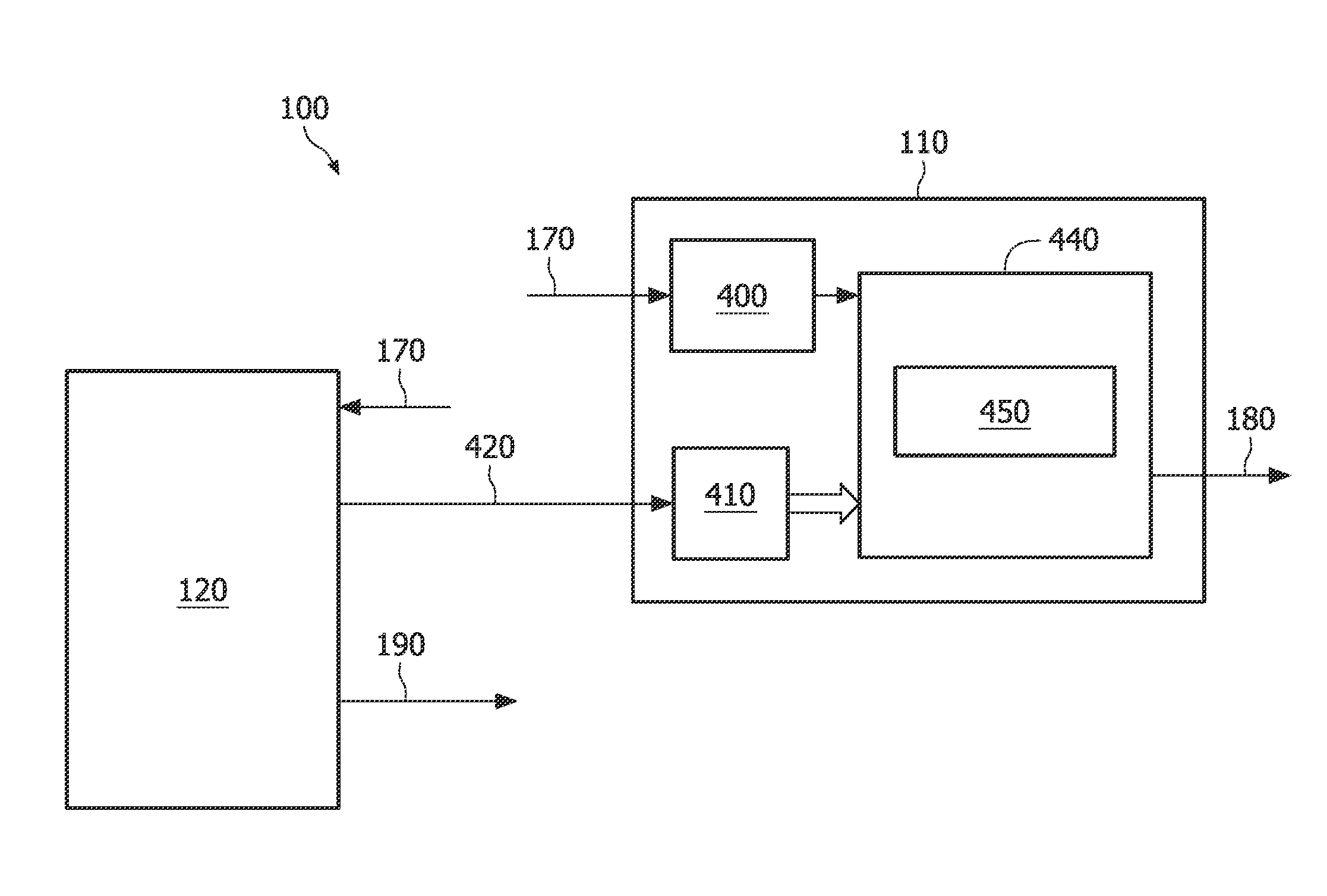
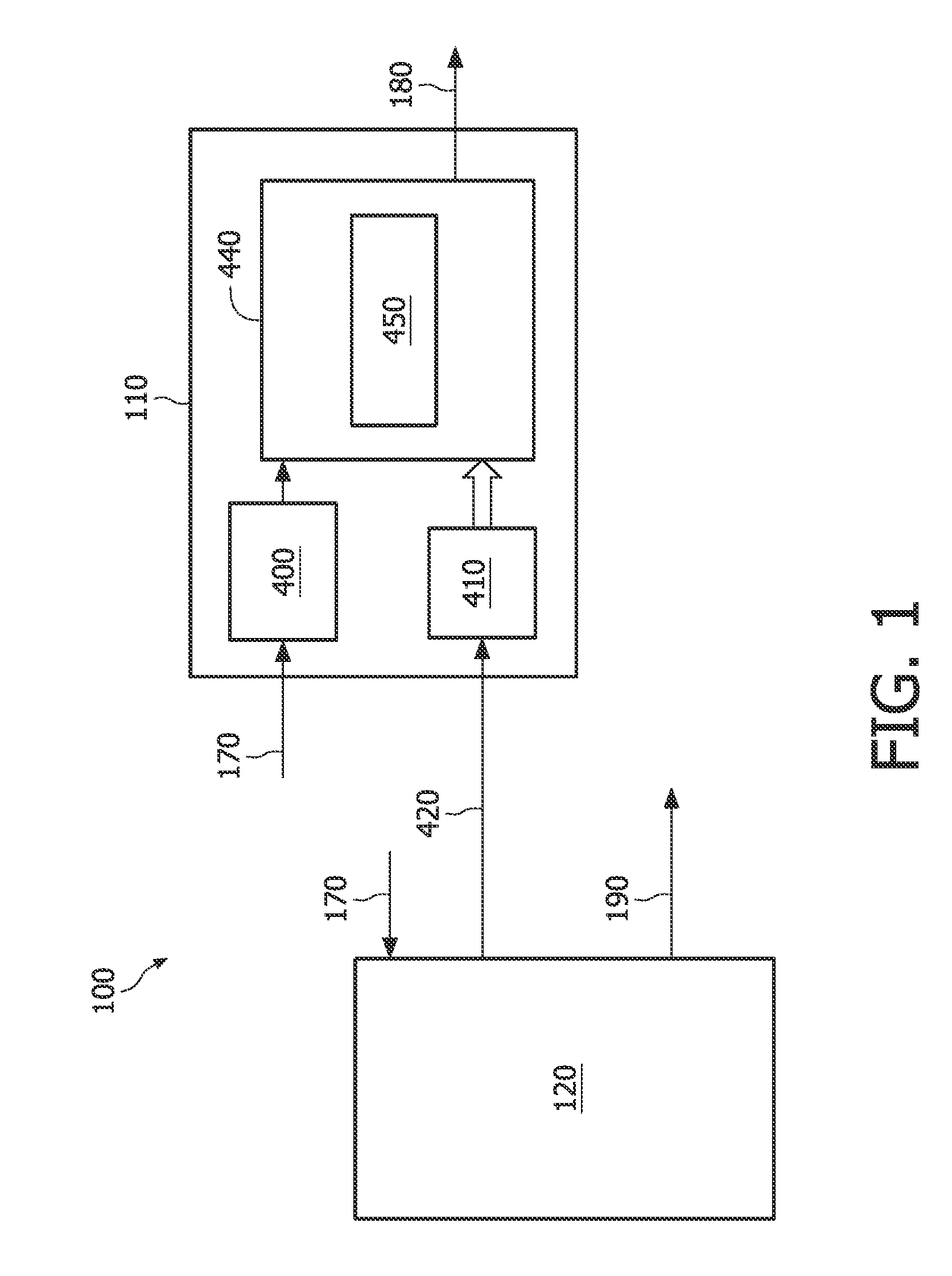
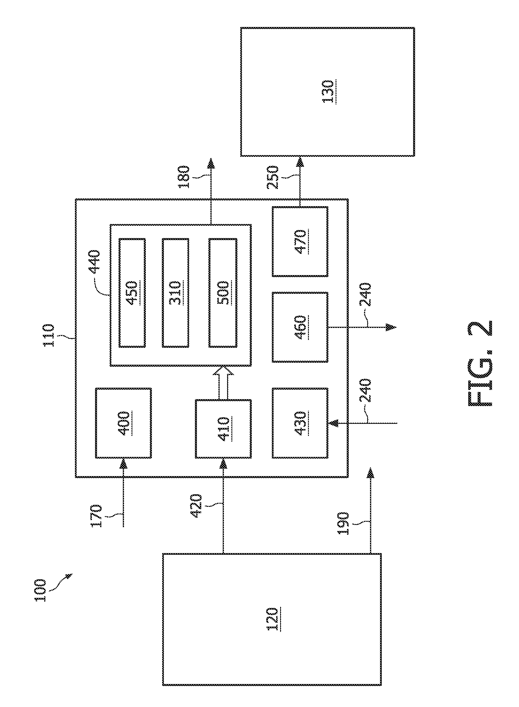
The invention provides a network device that can synchronize with another network device using a modified version of the "cyclic counts" method. This reduces energy consumption by minimizing the computational effort required for synchronization. The network device detects an event and receives a timestamp from the other network device. It then adjusts a counter to count from a start count to an end count and provide the signal based on the counter reaching the end count. The end count is modified based on the first and second timestamps, and the signal is advanced or delayed in time to synchronize with the further signal. This ensures that each network device has the same reference for time, reducing latency and improving efficiency in the network.

Problems solved by technology

However the local clock of the receiving network device may drift away from time to time from the local clock of the sending network device causing a recurring need to synchronize said local clocks.
Each clock synchronization requires the exchange of time stamps and a sequence of calculations, and thus each synchronization causes energy consumption.
It is therefore a problem that while the available energy source of the network device may be limited the calculations involved in the time synchronization between network devices contribute to the energy consumption and a reduction of battery life.

Method used


Image

  • Network synchronization with reduced energy consumption
  • Network synchronization with reduced energy consumption
  • Network synchronization with reduced energy consumption

Examples


Embodiment Construction

[0030]The advances in micro electro-mechanical systems (MEMS) technology, in digital circuit design, integration and packaging, and in wireless communication are leading to smaller, cheaper and lower power sensing and computing devices. These advances enable a creation of networks comprising a plurality of tiny computing network devices interacting with the environment and communicating with each other.

[0031]An example of such a network may be a wireless sensor network used for monitoring applications, each one of the sensors being comprised in a network device and corresponding to a wireless node of the network. An example of a monitoring application is an application wherein wireless sensors are used to monitor the structural health of a building or a bridge. In another example wireless sensors may be used for constant monitoring of people having certain medical conditions.

[0032]In these applications the energy source of each network device will be limited and for many of these ne...


PUM


Abstract

A network (100) comprises at least a network device (110) and a further network device (120). The network device (110) arranged for detecting an event (170), for receiving a first timestamp (420) of the further network device and for taking a second timestamp. The network device is arranged for providing a signal (180) in dependence of a counter (450) reaching an end count. The network device arranged for synchronizing the signal (180) with a further signal (190) provided by the further network device (120) by adjusting a value of the end count (60) to a modified end count (230), the modified end count being in dependence of the first and second timestamp. After having provided the synchronized signal (180c, 180d) the value of the end count is re-adjusted from the modified end count to its value prior to the adjustment.

Description

FIELD OF THE INVENTION[0001]The invention relates to a network device for use in a network comprising at least the network device and a further network device, the network device and the further network device comprising means arranged for detecting an event, means for receiving a first timestamp of the further network device, and means for taking a second timestamp. The invention further relates to a network comprising at least two of said network devices. The invention further relates to a method for synchronization of a signal provided by a network device and a further signal provided by a further network device.BACKGROUND OF THE INVENTION[0002]A network device according to the opening paragraph may be used in a sensor network. Sensor networks require a common notion of time among the network devices. In ‘Time Synchronization in Sensor Networks: A survey’, by Fikret Sivrikaya et, al., IEEE Network, July / August 2004, time synchronization in wireless networks such as sensor network...

Claims


Application Information

Patent Timeline
Patent Type & Authority Patents(United States)
IPC IPC(8): H04J3/06
CPCH04J3/0638H04J3/0685
Inventor VAN DER STOK, PETRIS DESIDERIUS VICTORAOUN, MARCLAMBERT, NICOLAASCATALANO, JULIEN
Owner KONINK PHILIPS ELECTRONICS NV
Learn More