Crop residue clearing device

a technology of crop residue and clearing device, which is applied in the field of agricultural implements, can solve the problems of increasing erosion, less amenable, and high cost of approach, and achieves the effects of reducing soil penetration, reducing soil damage or destruction, and reducing crop debris

Active Publication Date: 2013-03-12
AG FOCUS LLC
View PDF75 Cites 84 Cited by
  • Summary
  • Abstract
  • Description
  • Claims
  • Application Information

AI Technical Summary

Benefits of technology

[0004]Accordingly, it is an object of the present invention to provide a crop residue clearing device which is adjustable in soil depth operation, less susceptible to damage or destruction upon impact with obstructions in the soil, and allows for reduced soil penetration while providing for efficient crop debris reduction and removal from the planting area with minimum soil disturbance.
[0005]It is another object of the present invention to attach a crop residue clearing device to mounting hardware on an agricultural implement's tool bar without impacting the operation, positioning or attachment of planting implements on the tool bar.
[0006]Yet another object of the present invention is to provide for the accurate soil depth operation of a crop residue clearing device without using a complicated and expensive hydraulic, pneumatic or electric depth control arrangement.

Problems solved by technology

However, this approach is expensive, time consuming and results in increased erosion from both rain and wind and runs counter to current federal government restrictions requiring that a certain amount of ground cover remain in place at all times in fields.
Planting in undisturbed soil and residue conditions is often less amenable to ensuring uniform seed depth and placement.
However, the no-till or minimum till approach results in field and soil conditions which are less amenable to the planting of crops.
For example, the field surface cover is typically non-uniform and the increased crop residue remaining in the no-till or minimum till fields is more likely to result in fouling of the planting implements and non-uniformity in the depth, spacing and alignment of the rows of planted seed.

Method used


Image

  • Crop residue clearing device
  • Crop residue clearing device
  • Crop residue clearing device

Examples


Embodiment Construction

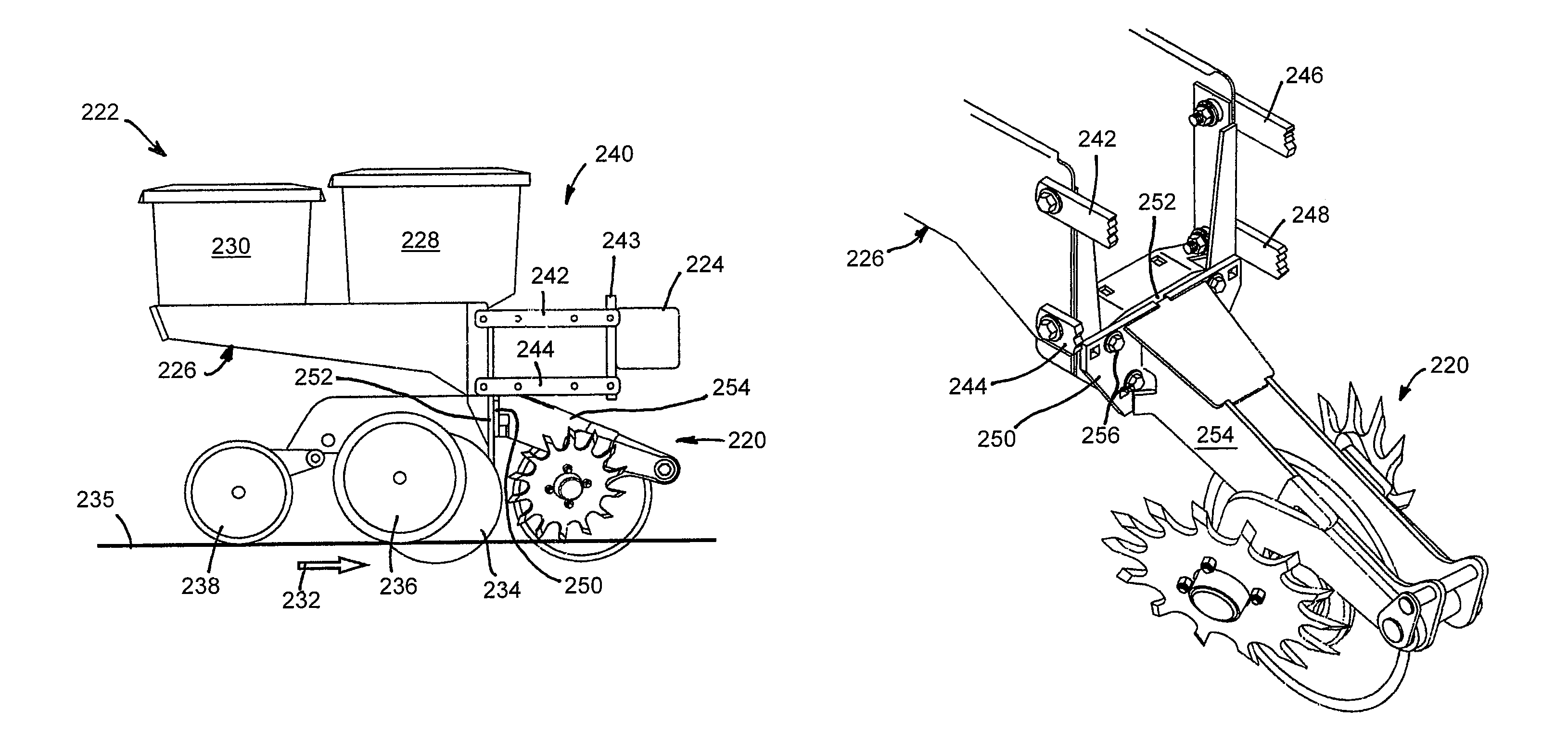
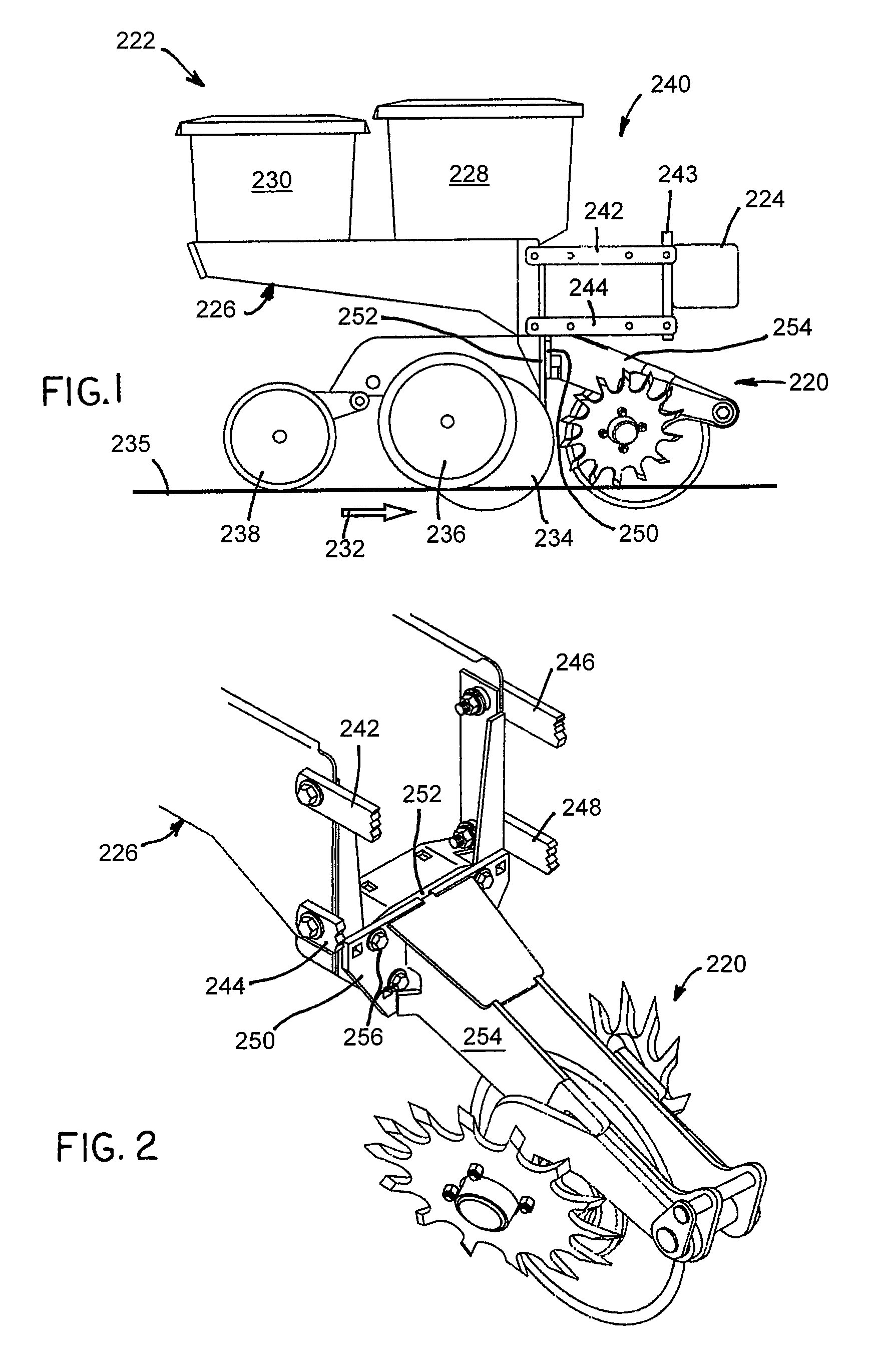
[0029]Referring to FIG. 1, there is shown a side elevation view of a conventional planter unit 222 to which is directly mounted the crop residue clearing device 220 in accordance with one embodiment of the present invention. FIG. 2 is an upper perspective view of the mounting arrangement for attaching the crop residue clearing device 220 to a forward portion of the planter unit 222. Planter unit 222 may include many elements, but for purposes of describing the present invention, the planter unit is shown as including a frame 226 to which are mounted a seed hopper 228, an insecticide hopper 230, and plural ground engaging members. The illustrated ground engaging members include a pair of laterally spaced furrow opening discs (where one disc is shown as element 234), plural gauge wheels (where one gauge wheel is shown as element 236), and a trailing furrow closing wheel 238. All of the aforementioned ground engaging members either ride on the surface of the soil 235, or penetrate the ...


PUM


Abstract

Apparatus for clearing crop residue from a field is adapted for attachment to a tool bar of an agricultural implement or to a planter unit such that the apparatus is pulled through a field by the implement. The apparatus includes a support structure extending forward of the tool bar and at least one and preferably a pair of floating arms pivotally attached to a forward portion of the support structure and extending rearwardly, with a toothed wheel rotationally attached to an aft end of the arm(s). A coulter attached to the support structure is disposed between and extends forward of the soil-engaging toothed wheel(s) and in combination with the wheel(s) severs and removes residue in the seeding pathway. An adjustable biasing arrangement urges the toothed wheels, either in unison or independently, downwardly into engagement with the soil. Upper and lower stop limits are provided to limit vertical positioning of the toothed wheel(s).

Description

FIELD OF THE INVENTION[0001]This invention relates generally to agricultural implements, and is particularly directed to apparatus for clearing crop residue from over the planting row with minimal soil disturbance.BACKGROUND OF THE INVENTION[0002]Agricultural practices over the last several decades have changed from complete, deep or broadcast tillage prior to planting to strip-till or direct (no-till) planting. Tillage passes provide relatively smooth, non-compacted and generally uniform soil and crop residue conditions to facilitate uniform seed depth and placement during planting. However, this approach is expensive, time consuming and results in increased erosion from both rain and wind and runs counter to current federal government restrictions requiring that a certain amount of ground cover remain in place at all times in fields. The more recent approach of direct planting results in reduced erosion and reduced costs in terms of fuel required to operate the field preparation a...

Claims


Application Information

Patent Timeline
Patent Type & Authority Patents(United States)
IPC IPC(8): A01B49/04
CPCA01B35/16A01B35/28A01C7/006Y02P60/20
Inventor FREED, BRIAN E.
Owner AG FOCUS LLC
Why Eureka
Try Eureka