
Self-locking screw connection

a screw connection and self-locking technology, applied in the direction of screws, threaded fasteners, fastening means, etc., can solve the problems of stiffness of the screw connection, the nut can be loosened only with difficulty, and the thread between the screw section and the nut can be restricted in terms of its mobility, so as to achieve the effect of easy rotation or removal of the screw section, high resolution of the axial position, and high resolution of the pitch angle of the nu

Active Publication Date: 2013-03-12
NEUMAYER TEKFOR ENG GMBH
View PDF9 Cites 2 Cited by
  • Summary
  • Abstract
  • Description
  • Claims
  • Application Information

AI Technical Summary

Benefits of technology

[0006]A further object of the invention is to provide a self-locking screw connection that can be easily produced.
[0007]Yet another object of the invention is to provide a self-locking screw connection that can be easily mounted.
[0008]A still further object of the invention is to provide a self-locking screw connection that can be precisely adjusted.
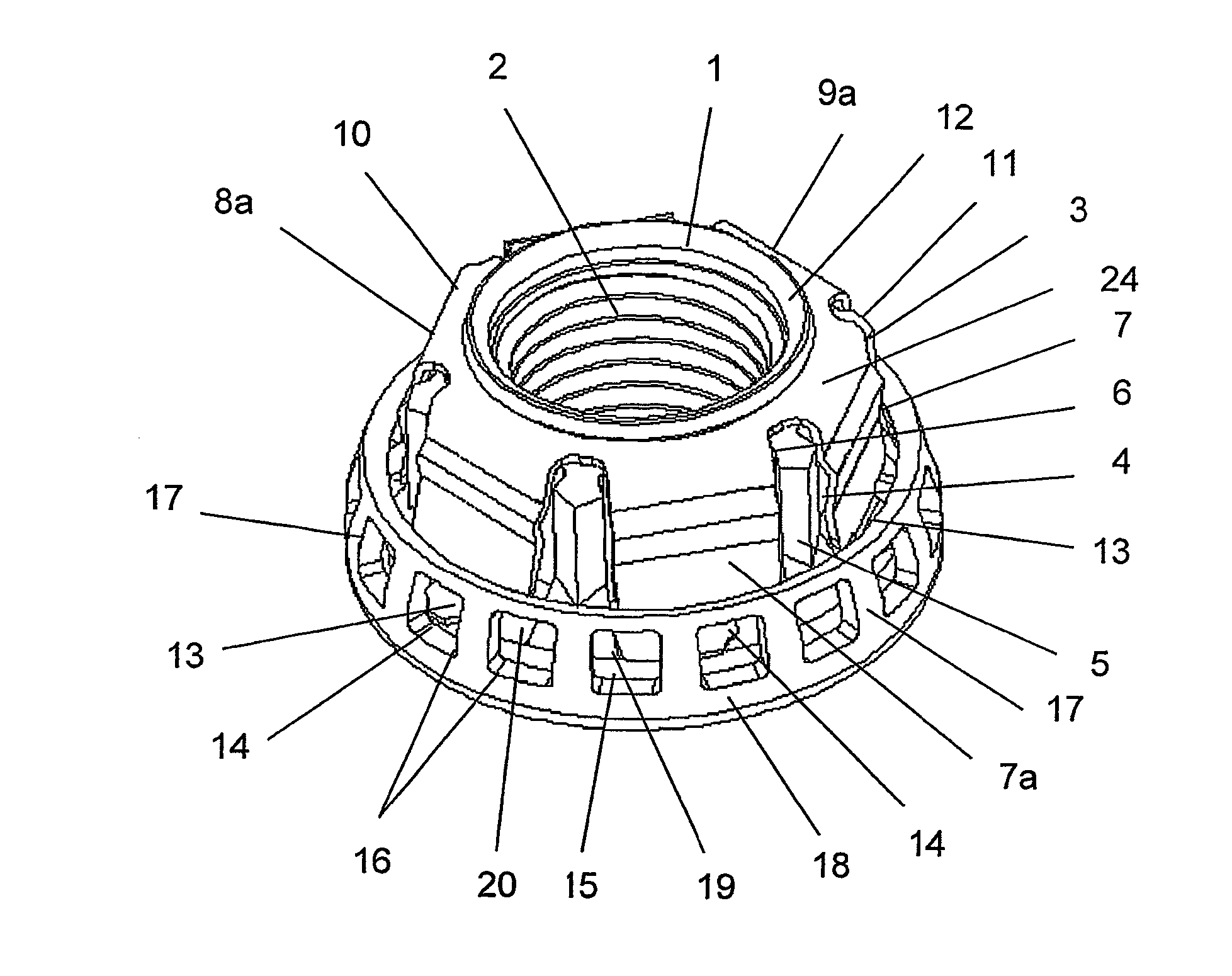
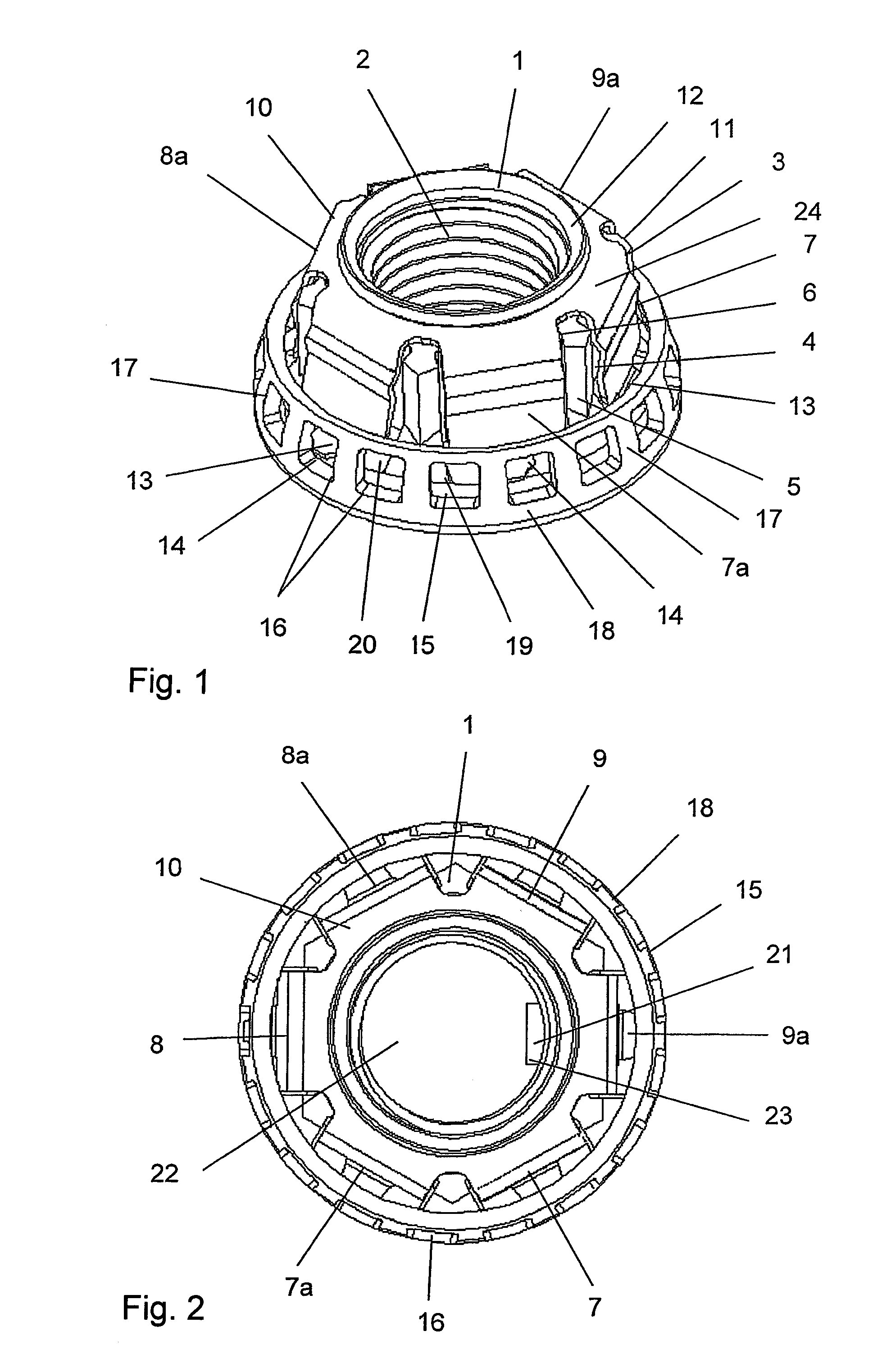
[0010]It has proved particularly advantageous if a plurality of catches are provided that are made of a sheet-metal component and that extend axially along the respective associated surface of the polygon and the free ends of which comprise engagement profiles such as hooks that can form a positive lock with the grid. For example, the sheet-metal component that can be provided with the corresponding shape by punching and bending processes can comprise an annular collar, through which the screw section is guided with play and which is attached to the end face of the nut that is oriented away from the intermediate washer in that, for example, a rim provided for this purpose or corresponding axially designed webs that are distributed around the circumference are beaded over. In this way, the sheet-metal component can comprise one to six, preferably three to six catches, for example, in the case of a polygon forming a hexagon, which catches are edge-beaded along the surfaces of the hexagon, the edge-beading resulting in the adjustment of pre-stress such that when the catches are unstressed, they form an inclined angle relative to the surfaces of the hexagon, which inclined angle is sufficient for the end profiles of the catches to engage the grid and form a positive lock with the grid. When the screwing tool, for example a nut screwer or a socket wrench, is applied to the polygon, the catches bear against the surface of the polygon and the positive lock with the grid is released so that the nut can be rotated easily on the screw section or removed from the screw section.
[0011]It has proved particularly advantageous if recesses are provided in the surfaces of the polygonal body of the nut, in which recesses the catches can be received when stressed by the screwing tool, thereby forming an effective contact pattern for the screwing tool on the polygonal body of the nut. Furthermore, a bead, for example a shaft that is raised radially from the catch surface, can be provided in the catches, which shaft optionally compensates for a play between the screw tool and the catch surface and enables a complete release of the positive lock between the catches and the grid even if the polygonal body of the nut is not completely inserted into the screwing tool.
[0012]In order to form the grid of the intermediate washer, the washer may comprise radially outwardly oriented tongues that are distributed around the outer circumference of the intermediate washer and that are bent around a circular base or flange of the nut to form the grid and the intermediate washer is mounted on the nut so as to be able to rotate and yet is secured against loss. When the screwing tool is not placed on the polygon, the catches relax and move radially outwardly into the intermediate gaps of the grid formed by the tongues of the intermediate washer and thereby prevent rotation of the intermediate washer relative to the nut. When the screwing tool is applied to the polygonal body of the nut, the catches are resiliently compressed into the recesses in the surfaces of the polygon. The grid can also be realized by holes that are punched around the base of the nut and that are distributed over the circumference.

Problems solved by technology

The thread between the screw section and the nut can be restricted in terms of its mobility, for example, by a plastic insert, which leads to stiffness of the screw connection.
Furthermore, these self-locking nuts can be loosened again only with difficulty once they are snap-fitted during the screwing process.
In the case of self-locking nuts, it is often only possible to achieve an insufficient resolution of the pre-stress to be provided or an axial play of the nut to be adjusted.

Method used


Image

  • Self-locking screw connection
  • Self-locking screw connection

Examples


Embodiment Construction

[0019]FIG. 1 shows the self-locking nut 1 of the screw connection which is not depicted in its entirety. Nut 1 comprises an internal thread 2 in which the screw section is screwed. In the illustrative embodiment shown, a polygonal body 3 for rotating the nut 1 by a screwing tool is in the form of a hexagon comprising lateral surfaces 4, 5, each of which comprises a recess 6 into which the catches 7, 7a, 8, 8a, 9, 9a can be received. The catches 7, 7a, 8, 8a, 9, 9a are attached to a common annular collar 10 or mounted as a single part thereon, and the annular collar 10 is permanently connected to the end face 11 of the nut 1. In the illustrative embodiment shown, the annular collar 10 is centered on an annular web 12 that is beaded over in order to secure the annular collar 10 in the axial direction.

[0020]The annular collar 10 comprising the catches 7, 7a, 8, 8a, 9, 9a forms a single integral component 24 and is made of a resiliently elastic material such as spring-steel metal sheet....


PUM


Abstract

A screw connection having a screw section and a nut threaded thereon. A self-locking effect of the nut on the screw section is achieved in a simple manner in that an intermediate disk is supported non-rotatably on the screw section and is received on the nut so as to be rotatable relative to the nut. The intermediate disk includes a grid distributed around the circumference of the intermediate disk, and the nut carries at least one resiliently elastic, radially displaceable catch formed by a sheet-metal part which, after installing the nut, positively engages the grid to lock the nut against rotation relative to the screw section and intermediate disk. Upon application of a wrench to the nut, the at least one resilient, radially displaceable catch is compressed and drawn out of engagement with the grid, so that the nut can be rotated relative to the screw section.

Description

CROSS REFERENCE TO RELATED APPLICATIONS[0001]This application is a continuation of international patent application no. PCT / DE2009 / 001802, filed Dec. 23, 2009, designating the United States of America, and published in German on Jul. 22, 2010 as WO 2010 / 081450, the entire disclosure of which is incorporated herein by reference. Priority is claimed based on Federal Republic of Germany patent application no. DE 10 2009 005 334.4, filed Jan. 16, 2009, the entire disclosure of which likewise is incorporated herein by reference.BACKGROUND OF THE INVENTION[0002]The present invention relates to a self-locking screw connection comprising a screw section and a nut that is mounted on the screw section so as to be self-locked.[0003]Self-locking screw connections have been known for a long time. The thread between the screw section and the nut can be restricted in terms of its mobility, for example, by a plastic insert, which leads to stiffness of the screw connection. Alternatively, provision ...

Claims


Application Information

Patent Timeline
Patent Type & Authority Patents(United States)
IPC IPC(8): F16B39/10
CPCF16B39/02F16B39/106
Inventor SAVOY, JULIANOSIGOLI, PAULO CESARDE SOUZA, MAURO MORAES
Owner NEUMAYER TEKFOR ENG GMBH
Learn More