
Process for producing magnet

a technology of producing process and magnet, which is applied in the field of process for producing magnet, can solve the problems of complicated production conditions and difficulty in producing magnets with stabilized magnetic properties at a high yield, and achieve the effects of improving the corrosion resistance of the obtained magnet, satisfying diffusion, and sufficient squareness ratio

Active Publication Date: 2013-03-12
TDK CORPARATION
View PDF11 Cites 1 Cited by
  • Summary
  • Abstract
  • Description
  • Claims
  • Application Information

AI Technical Summary

Benefits of technology

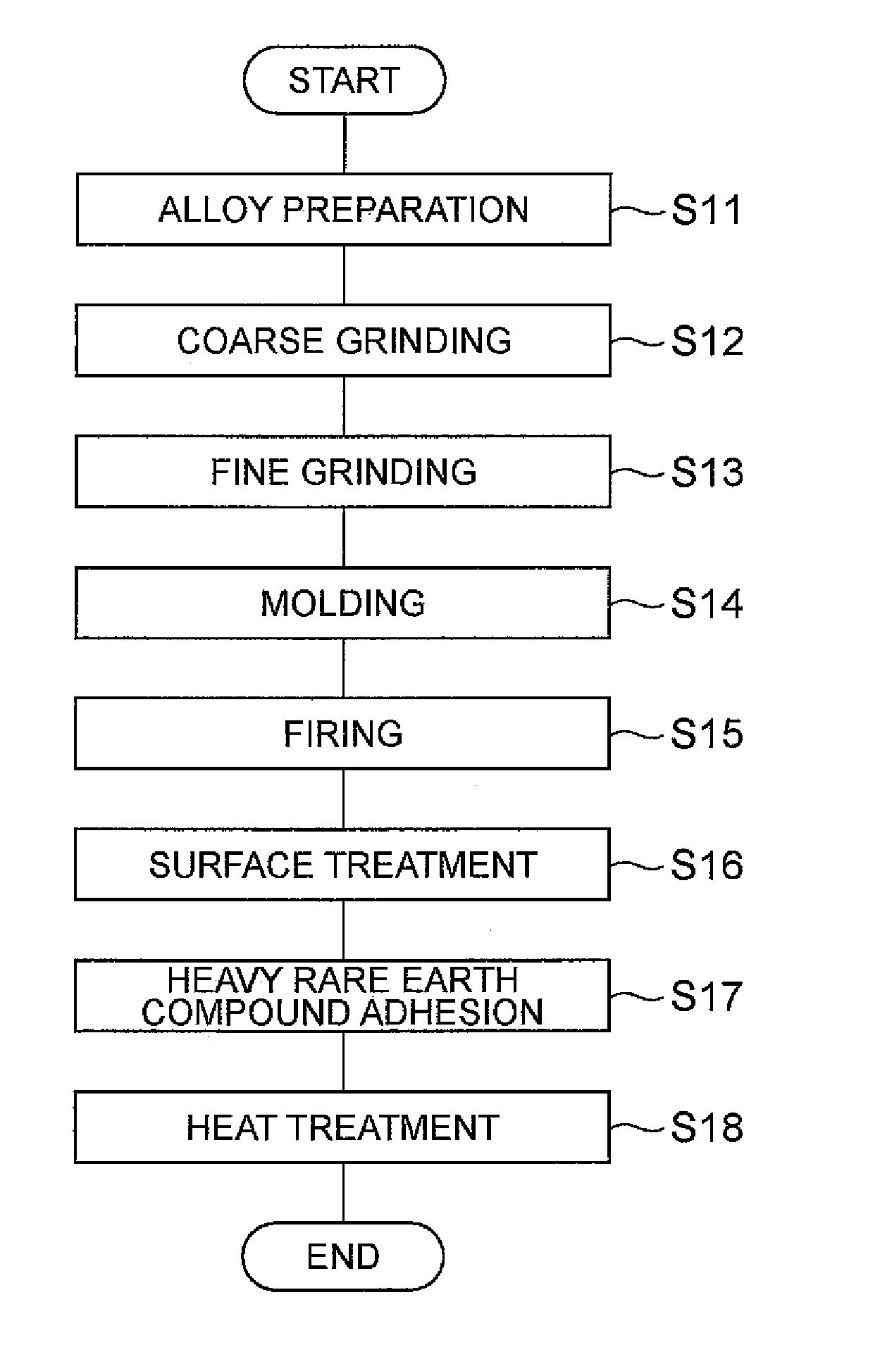
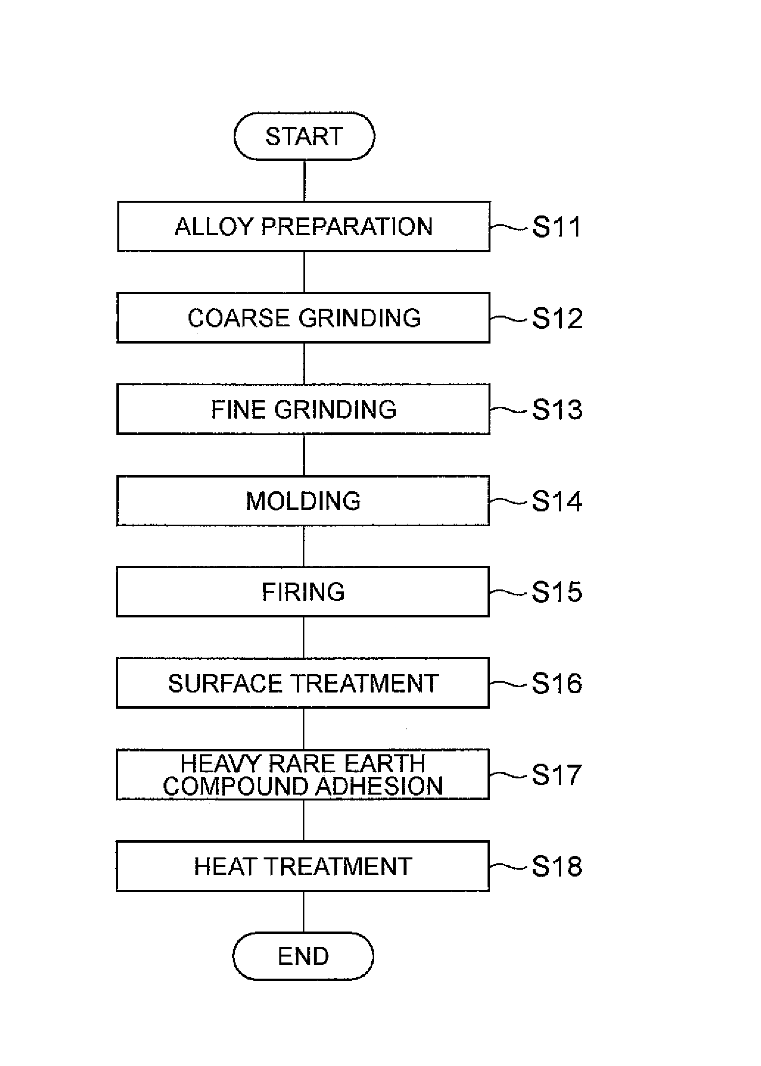
[0030]Next, the heavy rare earth compound containing the heavy rare earth element is adhered onto the surface of the surface treated sintered compact (step S17). The term “heavy rare earth element” refers to rare earth elements with high atomic numbers, and generally includes the rare earth elements from 64Gd to 71Lu. The heavy rare earth element in the heavy rare earth compound for this embodiment is Dy or Tb. According to this embodiment, only iron compounds of the heavy rare earth elements are used as heavy rare earth compounds, whereas heavy rare earth element compounds other than iron compounds, such as oxides, halides or hydroxides, are not used. As specific heavy rare earth compounds there may be mentioned DyFe, TbFe, DyFeH and TbFeH. The heavy rare earth compound according to the invention is an alloy of iron with Dy or Tb, and it does not have the excellent high magnetic properties of ordinary magnets. The Dy or Tb content in the heavy rare earth compound is preferably 60-95 wt %. When the heavy rare earth compound is DyFe or TbFe, the Dy or Tb content is more preferably 65-95 wt % and even more preferably 70-92 wt %. When the heavy rare earth compound is DyFeH or TbFeH, the Dy or Tb content is more preferably 64-94 wt % and even more preferably 69-91 wt %. A portion of the Fe in the heavy rare earth compound may be replaced with Co, Al or Cu, in a range such that the effect of the invention is still exhibited.
[0031]The heavy rare earth compound adhered onto the sintered compact is preferably in granular form, with a mean particle size of preferably 100 nm-50 μm and more preferably 1 μm-10 μm. If the particle size of the heavy rare earth compound is less than 100 nm, the amount of heavy rare earth compound diffused in the sintered compact by the heat treatment will be excessive, potentially resulting in insufficient Br in the obtained rare earth magnet. If it is greater than 50 μm, on the other hand, the heavy rare earth compound will not diffuse easily in the sintered compact, and the HcJ may not be sufficiently improved.
[0032]The method of adhering the heavy rare earth compound onto the sintered compact may be, for example, a method in which particles of the heavy rare earth compound are directly blasted onto the sintered compact, a method in which a solution of the heavy rare earth compound in a solvent is applied onto the sintered compact, or a method in which a slurry of the heavy rare earth compound particles dispersed in a solvent is applied onto the sintered compact. Of these, the method of applying a slurry onto the sintered compact is preferred since it allows the heavy rare earth compound to be more evenly adhered onto the sintered compact and results in satisfactory diffusion in the heat treatment described hereunder.
[0033]The solvent used for the slurry is preferably an alcohol, aldehyde, ketone or the like that can evenly disperse the heavy rare earth compound without dissolving it, and ethanol is preferred. Application of the slurry onto the sintered compact may be accomplished by dipping the sintered compact into the slurry, or by dropping the slurry onto the sintered compact.
[0034]When a slurry is used, the content of the heavy rare earth compound in the slurry is preferably 5-50 wt % and more preferably 5-30 wt %. If the content of the heavy rare earth compound in the slurry is too low or too high, it may be difficult to achieve uniform adhesion of the heavy rare earth compound onto the sintered compact, potentially making it impossible to obtain a sufficient squareness ratio. If it is too high, the surface of the sintered compact may be roughened and it may be difficult to form a plating for improved corrosion resistance of the obtained magnet.
[0035]Components other than heavy rare earth compounds may also be included in the slurry if necessary. As examples of other components to be included in the slurry there may be mentioned dispersing agents to prevent aggregation of the heavy rare earth compound particles.

Problems solved by technology

Moreover, the processes described in Japanese Patent Application Laid-open No. 2005-285860, Japanese Patent Application Laid-open No. 2005-285861 and Japanese Patent Application Laid-open No. 2005-209932 have required special production equipment due to their use of molten alloys, and this has tended to complicate the conditions for production.
In addition, when heat treatment is carried out at high temperatures of above 1000° C. there is a greater influence by temperature variation during the heat treatment, and due to potential grain growth and excess diffusion of the elements by the heat treatment, it is difficult to produce a magnet with stabilized magnetic properties at a high yield.

Method used


Image

  • Process for producing magnet
  • Process for producing magnet

Examples


example 1

[0042]First, a starting alloy was prepared to produce a rare earth magnet having the composition 23.50 wt % Nd-3.50 wt % Dy-3.30 wt % Pr-0.450 wt % Co-0.18 wt % Al-0.06 wt % Cu-0.97 wt % B-bal.Fe. Two starting alloys were prepared, a main phase alloy primarily for formation of the main phase of the magnet, and a grain boundary alloy primarily for formation of the grain boundary. Next, the starting alloys were subjected to coarse grinding by hydrogen grinding and then jet mill grinding with high pressure N2 gas to produce fine powders each with mean particle sizes of D=4 μm.

[0043]The fine powder for the main phase alloy and the fine powder for the grain boundary alloy were mixed in a proportion of 95:5, respectively, to prepare a magnetic powder as the starting powder for the rare earth magnet. The magnetic powder was then used for magnetic field molding under conditions with a molding pressure of 1.2 t / cm2 and an orienting magnetic field of 15 kOe, to obtain a compact. The obtained ...

examples 2-6

[0047]Rare earth magnets were produced in the same manner as Example 1, except that the DyFe composition was changed to the compositions shown in Table 1.

example 7

[0048]A rare earth magnet was produced in the same manner as Example 1, except that DyNdFe having the composition shown in Table 1 was used instead of DyFe.


PUM

PropertyMeasurementUnit
particle sizeaaaaaaaaaa

Abstract

The process for producing a magnet according to the invention is characterized by comprising a first step in which a heavy rare earth compound containing Dy or Tb as a heavy rare earth element is adhered onto a sintered compact of a rare earth magnet and a second step in which the heavy rare earth compound-adhered sintered compact is subjected to heat treatment, wherein the heavy rare earth compound is a Dy or Tb iron compound.

Description

BACKGROUND OF THE INVENTION[0001]1. Field of the Invention[0002]The present invention relates to a process for producing a magnet, and more specifically it relates to a process for producing a rare earth magnet containing a rare earth element.[0003]2. Related Background Art[0004]Rare earth magnets with R—Fe—B (=rare earth element) based compositions exhibit excellent magnetic properties, and much research is being devoted to further improving their magnetic properties. Residual flux density (Br) and coercive force (HcJ) are generally used as indices of the magnetic properties of magnets. It is known in the art that the HcJ value of a rare earth magnet can be improved by adding Dy or Tb.[0005]However, since the saturation magnetization of an R—Fe—B based compound is lowered when an element such as Dy or Tb is selected as R, its addition in an excessive amount will tend to reduce the Br value. A method for minimizing this inconvenience has been disclosed in International Patent Public...

Claims


Application Information

Patent Timeline
Patent Type & Authority Patents(United States)
IPC IPC(8): B05D7/14B22F3/00
CPCH01F41/0293H01F41/026
Inventor BABA, FUMITAKANAKAMURA, HIDEKITANAKA, SATOSHIMASUDA, TAKESHI
Owner TDK CORPARATION
Learn More