High-Strength Structure

a structural system and high-strength technology, applied in the direction of walls, building roofs, foundation engineering, etc., can solve the problems of staggering tax burden, blundering, and prolific destruction, and achieve the effect of uniform and consistent wall-to-floor conta

Inactive Publication Date: 2011-07-07
STANLEY NEWMAN
View PDF33 Cites 6 Cited by
  • Summary
  • Abstract
  • Description
  • Claims
  • Application Information

AI Technical Summary

Benefits of technology

[0007]The fiber-reinforced membrane layer comprises a roving member that is cured and continuously bonded over the entire surface of the rigid foam core. The outer membrane layer is coated with a continuous and uniform application of a resin based, high-strength bonding agent. The bonding agent is formed by using a resin with a polymer base with water as the solvent. This resin will emit no noxious odor or toxic fumes, and when it is cured, the resin will form a vapor-tight barrier on the panel. The resin-based bonding agent is uniformly and continuously applied over the surface of the rigid foam core to create a uniform bond between the fiber-reinforced membrane layer and the rigid foam core, forming a rigid composite panel.
[0009]Throughout the structure, the panels are placed at a vertical orientation to form walls. A high-strength “T” connection of the external and internal walls comprises two rows of threaded fasteners connected to a rivnut providing a clamping force to both the outer layer and inner layer of the panel spacers. A compression sleeve is used to brace the panel spacers against the compression force generated by the fasteners. A high-strength “L” corner connection of two walls using the same method, except with one row of fasteners instead of two rows. In embodiments having metal components, a bonding agent can be applied in areas of metal-to-metal contact to make the connection strong, leak tight, and rigid.
[0010]The high-strength foundation connection of the walls to the foundation. This connection comprises a continuous seam plate with bonding agents, mechanical fasteners, and a metal bearing cap having continuously spaced, angle-shaped anchor studs welded to the metal bearing cap. When the foundation is poured or cured, the bearing cap is placed continuously around the edge of the uncured foundation slab to assure sufficiently uniform and consistent wall to floor contact. The wall, which has a panel spacer at the bottom of the wall, is bonded to the bearing cap via the high-strength bonding agent. Preferably, the bonding agent should also provide corrosion protection where steel is used as a panel spacer in the wall. After the wall is bonded to the bearing cap, the continuous seam plate is placed over the wall and foundation and attached via mechanical fasteners and additional bonding agents.
[0012]The high-strength eave is comprised of a horizontal soffit panel connected to an inclined eave panel, thus forming a triangular truss. The interface between the soffit and eave panels can have a continuous sheet metal cap to protect and further strengthen the soffit and roof panel connection and to enhance the resistance of the roof sheeting to be lifted by the wind forces. The soffit panel connects to the top of the wall, and the inclined eave panel connects to the roof via the inclined portion of the connection bracket.

Problems solved by technology

In recent years, hurricanes have caused billions of dollars in damage by decimating many homes in the coastal regions of the Carolinas and Gulf states.
The destruction is caused by high wind forces and flooding due to excessive rain and high storm surges.
Follow up cost estimates by local officials revealed staggering tax burden to provide temporary shelter for habitants of destroyed homes, and to provide emergency repair of damaged homes.
The destruction has been so prolific that some of the largest insurance companies no longer offer new homeowner policies in coastal states.
Moreover, recent earthquake events have resulted in a devastating loss of life and property destruction where homes and buildings lack the shear strength to with stand even earthquakes of average magnitude.

Method used


Image

  • High-Strength Structure
  • High-Strength Structure
  • High-Strength Structure

Examples


Embodiment Construction

[0025]With reference to the drawings, the invention will now be described with regard for the best mode and the preferred embodiment. In general, the invention comprises an integrated, high strength, lightweight building structure to withstand extreme loading events, such as flooding, seismic events measuring 8.0 on the Richter scale, and wind loads resulting from winds up to 250 miles per hour (Fujita Scale IV Tornado). In addition, the building structure is constructed from materials that resist wood destroying organisms, mildew, mold, rot, fire, and water damage.

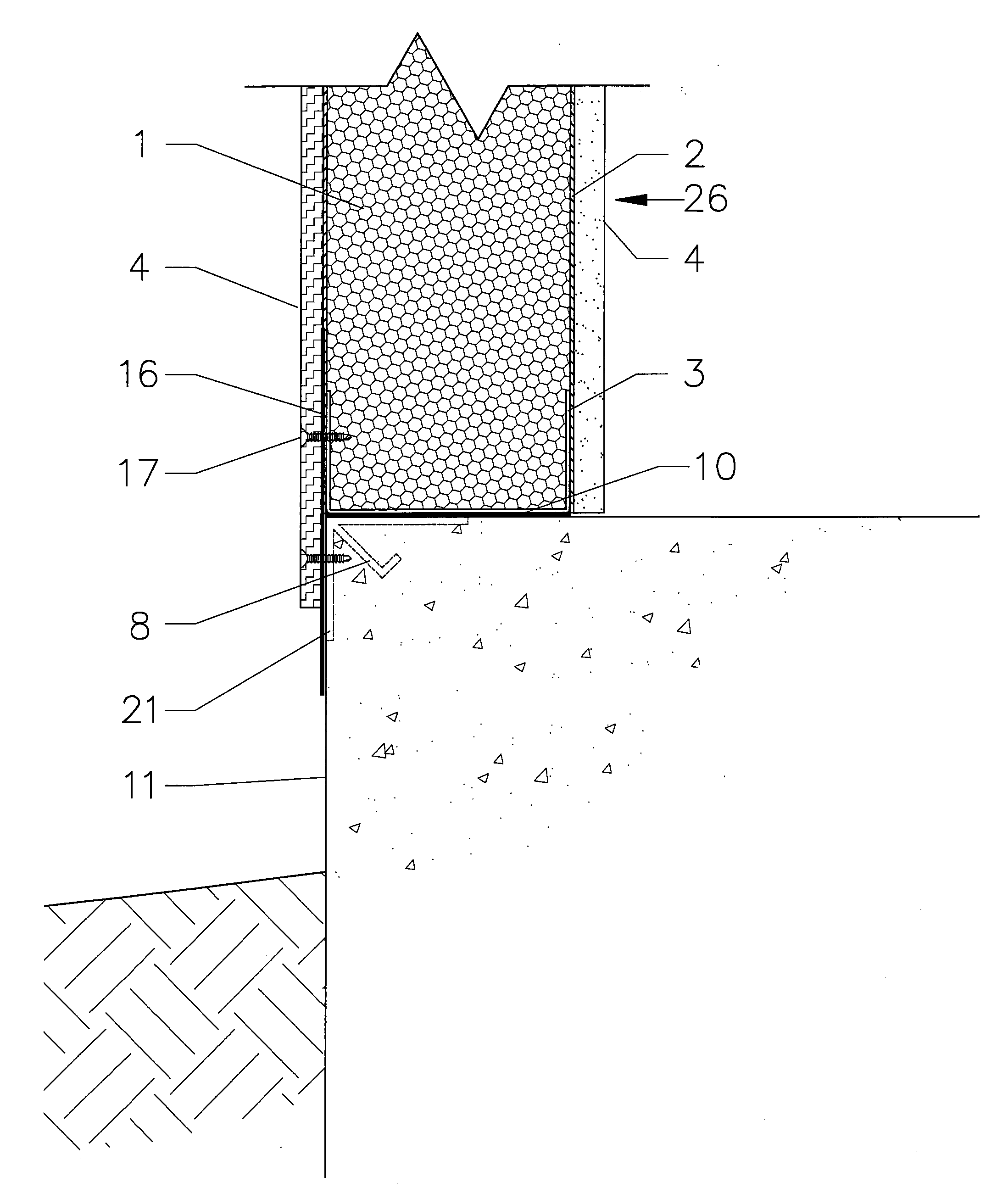
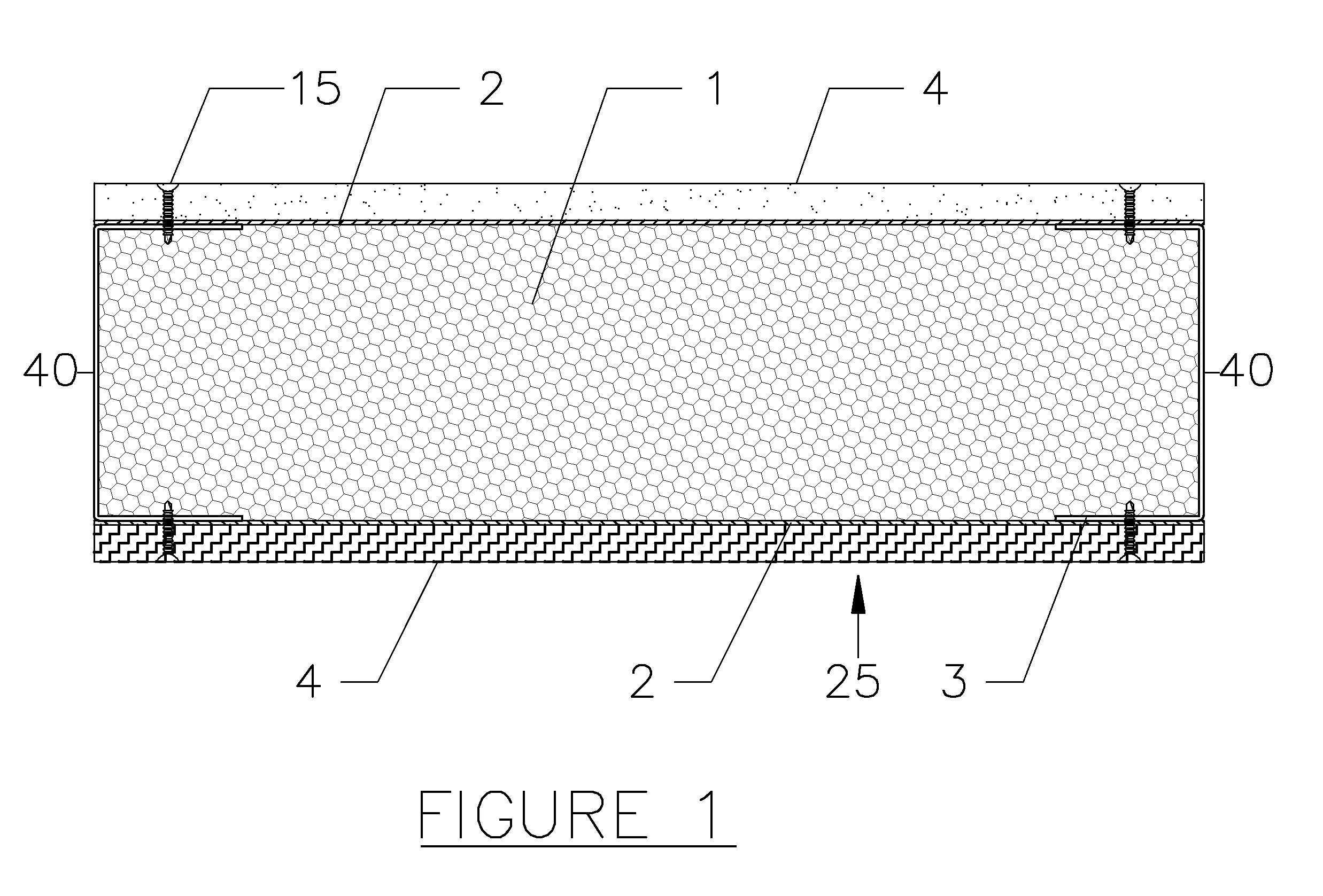
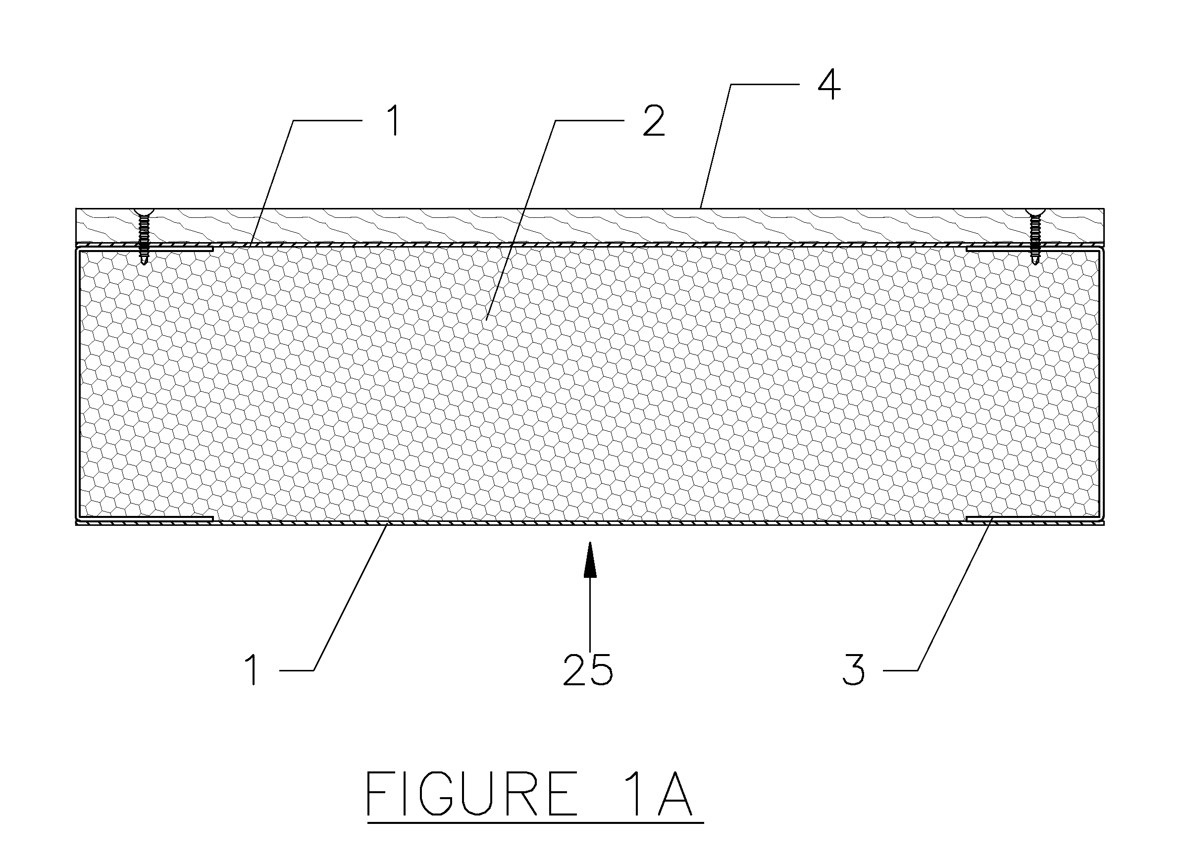
[0026]The high-strength structural system comprises a high-strength connection to a foundation 11, high-strength eaves, and high-strength structural panels 25. In the high-strength structural system, all panels for the walls 26, ceiling 27, roof 28, soffit 29, and eave 30 comprise the high-strength, fiber reinforced, laminated composite panels 25 discussed below. The foundation 11 can be any firm, stable surface, such as ...


PUM

PropertyMeasurementUnit
velocitiesaaaaaaaaaa
distanceaaaaaaaaaa
thicknessaaaaaaaaaa

Abstract

A high strength, lightweight building structure comprising a high-strength connection to a foundation, high-strength eaves, and high-strength structural panels. The fiber reinforced, high-strength structural panels form the walls, ceiling, roof, soffit, and eave of the structure. The panels comprise a rigid foam core having outer membrane layer, panel spacers, and sheeting. The high-strength foundation connection comprises a continuous seam plate with bonding agents, mechanical fasteners, and a metal bearing cap having continuously spaced, angle-shaped anchor studs welded to the metal bearing cap. The high-strength eave structure, comprise of a soffit panel connected to an inclined eave panel, a connection bracket and a rigid wedge continuously bonded between the ceiling panel and roof panel, thus forming a sealed, non-vented attic space.

Description

[0001]This application is a continuation-in-part of U.S. patent application Ser. No. 12 / 012,400, filed on Feb. 1, 2008, which received the benefit of U.S. Provisional Patent Application Ser. No. 60 / 898,916, filed on Feb. 1, 2007.BACKGROUND OF THE INVENTION[0002]The present invention relates generally to high-strength structural systems and components for residential and light commercial buildings, and more specifically to high-strength structural components for eaves, wall panels, ceiling panels, and roof panels. Also included are methods of attaching the components together, thereby forming a high strength integrated structure or enclosure.[0003]In recent years, hurricanes have caused billions of dollars in damage by decimating many homes in the coastal regions of the Carolinas and Gulf states. The destruction is caused by high wind forces and flooding due to excessive rain and high storm surges. A survey of the damage indicates that the wind velocities reached or exceeded 200 mile...

Claims


Application Information

Patent Timeline
Patent Type & Authority Applications(United States)
IPC IPC(8): E04B2/00E02D27/32
CPCE04B1/14E04B7/04E04C2/292E04D13/1625E04C2/34E04C3/36E04C2/296
Inventor STANLEY, NEWMAN
Owner STANLEY NEWMAN
Why Eureka
Try Eureka