Method of lost-wax manufacture of an annular bladed turbomachine assembly, metal mould and wax model for implementing such a method

a technology of annular bladed stator and metal mould, which is applied in the manufacture of tools, foundry patterns, and moulding apparatus, etc., can solve the problems of increasing the cost of annular bladed assembly manufacturing, reducing the accuracy of wax model shape, and optimising the risk of core deformation

Active Publication Date: 2013-03-19
SN DETUDE & DE CONSTR DE MOTEURS DAVIATION S N E C M A
View PDF8 Cites 2 Cited by
  • Summary
  • Abstract
  • Description
  • Claims
  • Application Information

AI Technical Summary

Benefits of technology

[0015]One aim of the invention is notably to provide a simple, economic and efficient solution to these problems.

Problems solved by technology

During the injection of the wax the core is assembled on the metal mould such that it is held firmly in position, in order to limit optimally the risk of a deformation of the core under the pressure of the wax, which would impair the accuracy of the shape of the wax model, and consequently of the bladed assembly obtained at the end of the manufacturing method.
Since the presence of an aperture in this location is not desirable, this aperture is generally plugged by brazing or a comparable method.
However, this plugging operation increases the cost of manufacture of the annular bladed assemblies.
In addition, the presence of brazed parts in the internal shrouds of these assemblies causes in these shrouds irregularities of shape and structure which are such that they reduce the mechanical resistance and therefore the lifetime of these shrouds.
In addition, the core can sometimes be deformed under the pressure of the wax when the latter is injected, leading to expensive disposals.

Method used


Image

  • Method of lost-wax manufacture of an annular bladed turbomachine assembly, metal mould and wax model for implementing such a method
  • Method of lost-wax manufacture of an annular bladed turbomachine assembly, metal mould and wax model for implementing such a method
  • Method of lost-wax manufacture of an annular bladed turbomachine assembly, metal mould and wax model for implementing such a method

Examples


Embodiment Construction

[0015]One aim of the invention is notably to provide a simple, economic and efficient solution to these problems.

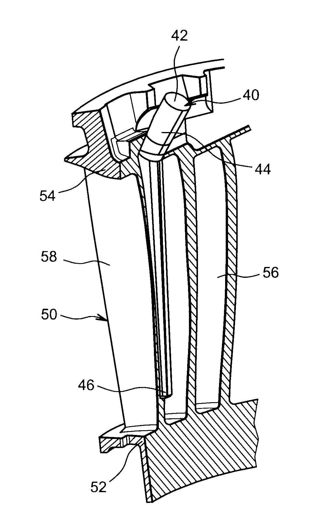
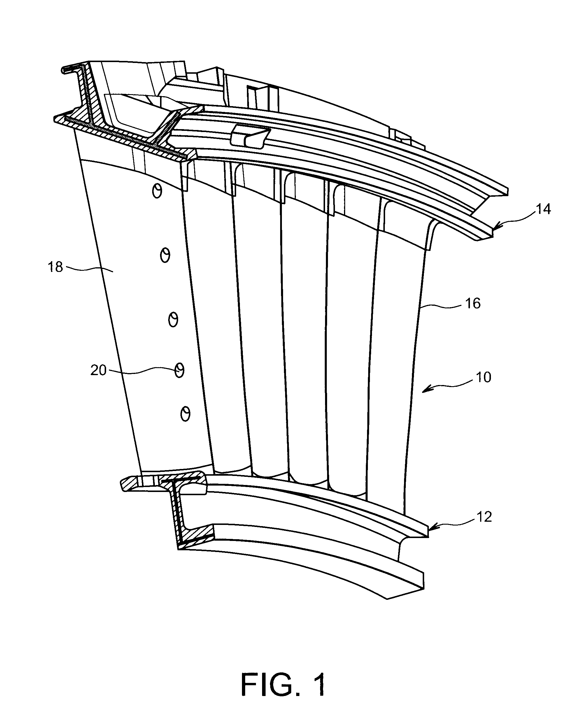
[0016]To this end it offers a method of manufacture of a wax model of an annular bladed turbomachine stator assembly, intended for manufacture of a mould of this bladed assembly, where the model includes two coaxial shrouds, respectively radially internal and radially external, which shrouds are connected to one another by multiple blades, at least one of which includes an internal cavity, where the said method includes, in succession, using a metal mould having roughly a shape to be given to the said model of an annular bladed assembly:

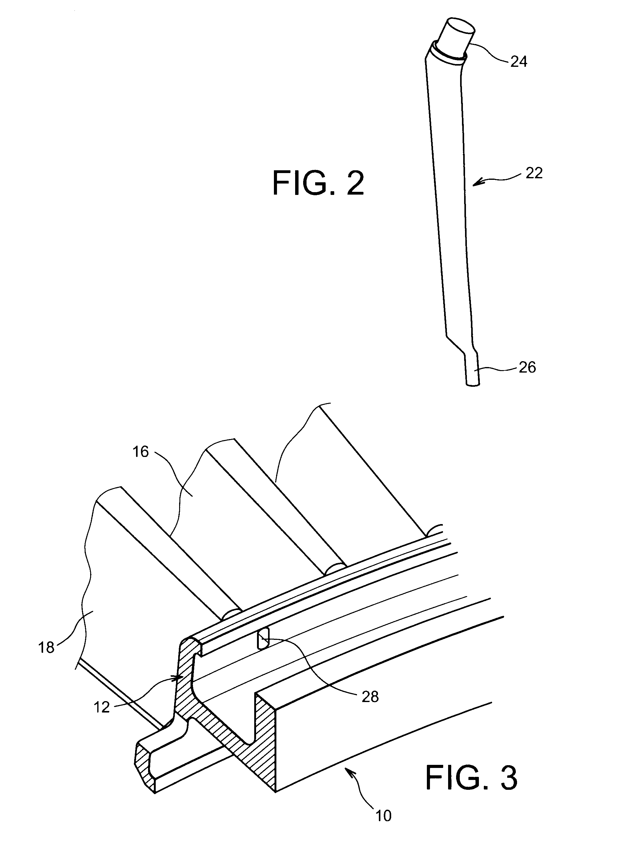
[0017]positioning of a core, intended to form the impression of the said cavity, in a portion of the said metal mould which defines the blade including the cavity, where the abovementioned core has a generally lengthened shape having a radially external end assembled on the metal mould;

[0018]injection of a wax in the metal mould fitted wit...


PUM

PropertyMeasurementUnit
shapeaaaaaaaaaa
refractoryaaaaaaaaaa
pressureaaaaaaaaaa

Abstract

A method of manufacture of a wax model of an annular bladed turbomachine stator assembly includes in succession the positioning, in a mold, of a core intended to form the impression of a cavity of a blade of the assembly, the injection of a wax in the mold, and the removal of the wax model fitted with the core from the mold. The core is manufactured in metal and is positioned such that its radially internal end is housed in the portion of the mold defining the blade including the cavity, away from the radially internal end of this portion of the mold.

Description

TECHNICAL FIELD[0001]The present invention concerns the manufacture of an annular bladed stator assembly for a turbomachine, such as an aircraft turbomachine.[0002]FIG. 1 represents such a bladed assembly 10, sometimes called an upstream or downstream guide vanes assembly, depending on its function within the turbomachine. This bladed assembly 10 typically includes two coaxial annular structures or shrouds, which are respectively internal 12 and external 14, and which are connected to one another by multiple blades 16.[0003]The invention concerns more specifically the manufacture of a bladed assembly including at least one blade 18 incorporating a cavity, of generally lengthened shape in the radial direction intended, for example, for measuring physical parameters, such as the pressure and temperature of the air flowing along the blade, possibly via apertures 20 of this blade.STATE OF THE PRIOR ART[0004]Turbomachines' bladed stator assemblies are generally manufactured by a casting ...

Claims


Application Information

Patent Timeline
Patent Type & Authority Patents(United States)
IPC IPC(8): B22C9/10B22C7/02B22C21/14
CPCB22C7/02B22C9/108F01D5/284F01D9/041B22C21/14F05D2230/21
Inventor BARIAUD, CHRISTIANCOLLIN, YANNICKHERZER, ERICMATHIEU, DAVID
Owner SN DETUDE & DE CONSTR DE MOTEURS DAVIATION S N E C M A
Why Eureka
Try Eureka