
Automobile caddy

a technology for automobiles and caddies, which is applied in the direction of washstands, chairs, lighting supports, etc., can solve the problems of affecting the safety of passengers, etc., and achieves the effect of high stability and a safe holding of items

Active Publication Date: 2013-03-19
SINGH NEERAJ
View PDF11 Cites 29 Cited by
  • Summary
  • Abstract
  • Description
  • Claims
  • Application Information

AI Technical Summary

Benefits of technology

The present invention is an auto caddy that can safely hold items in a vehicle, particularly when the vehicle is in motion. The caddy is attached to the back of a vehicle seat using slidable insertion of headrest seat posts for stability. The attachment members have multiple points of contact with the seat posts, making the caddy more stable and less likely to become dislodged. The caddy is designed to minimize manufacturing costs and optimize ease of assembly. The technical effects of the invention are improved stability and safety for holding items in a vehicle, especially during sudden movements.

Problems solved by technology

Typically, however, large drinks or top-heavy items housed in this kind of caddy may be easily dislodged and ejected from the caddy into the interior of the vehicle, potentially staining the vehicle interior or even causing injury to occupants where hot liquids are involved.
Additionally, use of this caddy precludes a middle rider in the front or rear of the vehicle because the caddy occupies the middle seat and the middle seatbelt.
Further, this type of caddy can generally only be used in vehicles that have a bench seat; it may not usually be used in vehicles with individualized bucket seats or consoles unless it is used in a primary seating position such as a passenger's seat, which is typically not feasible.
The primary problem with this kind of caddy is that it is only secured by the strap around the headrest post, leaving it free to shift and swing upon sudden stops, starts or sharp turns.
Where the caddy is of a type which is only secured at one point, however, the trash receptacle will swing out along with the caddy on sudden stops or starts, potentially causing a mess from spilled contents or at least annoying back seat passengers within range of the arc that the caddy or the bag.
Further, the trays that are typically incorporated in this kind of caddy are too small to be used as a workspace and too shallow to feasibly hold food during operation of the vehicle, making them generally impractical.
Finally, this kind of caddy makes it exceedingly difficult for back seat passengers to enter and exit their seats, especially if they must avoid bumping the caddy for fear of shifting it and spilling its contents.
Ideally the flaps are rubberized to prevent slippage with stops and starts, but top heavy drinks or other items still run the risk of ejection.
Further, severely sudden stops may still shift the caddy, especially where the friction coefficient between the rubber and the floorboard is not high enough to prevent slippage.
One other issue with many of the conventionally available automobile caddies is that they offer few, if any, options with regard to organization of the support it makes available.
Most have a limited number of features, include openings in predetermined sizes, and generally do not allow for customization with add-on components.
Often, however, this kind of caddy includes an extension arm which protrudes over the top edge of the seat, potentially causing discomfort to the passenger's head or neck or possibly even causing injury to a passenger's head or neck during sudden stops and starts, collisions, or any other incident which may force a passenger's head or neck onto the extension arms.
Additionally, if the strength of the vise mechanism is at all questionable, this kind of caddy may be easily dislodged with even a minimal amount of force, whether from bumping the unit during exit or entry or during a collision or other sudden movement of the vehicle.

Method used


Image

  • Automobile caddy
  • Automobile caddy
  • Automobile caddy

Examples


Embodiment Construction

[0035]The invention, its configuration, construction, and operation will be best further described in the following detailed description, taken in conjunction with the accompanying drawings in which:

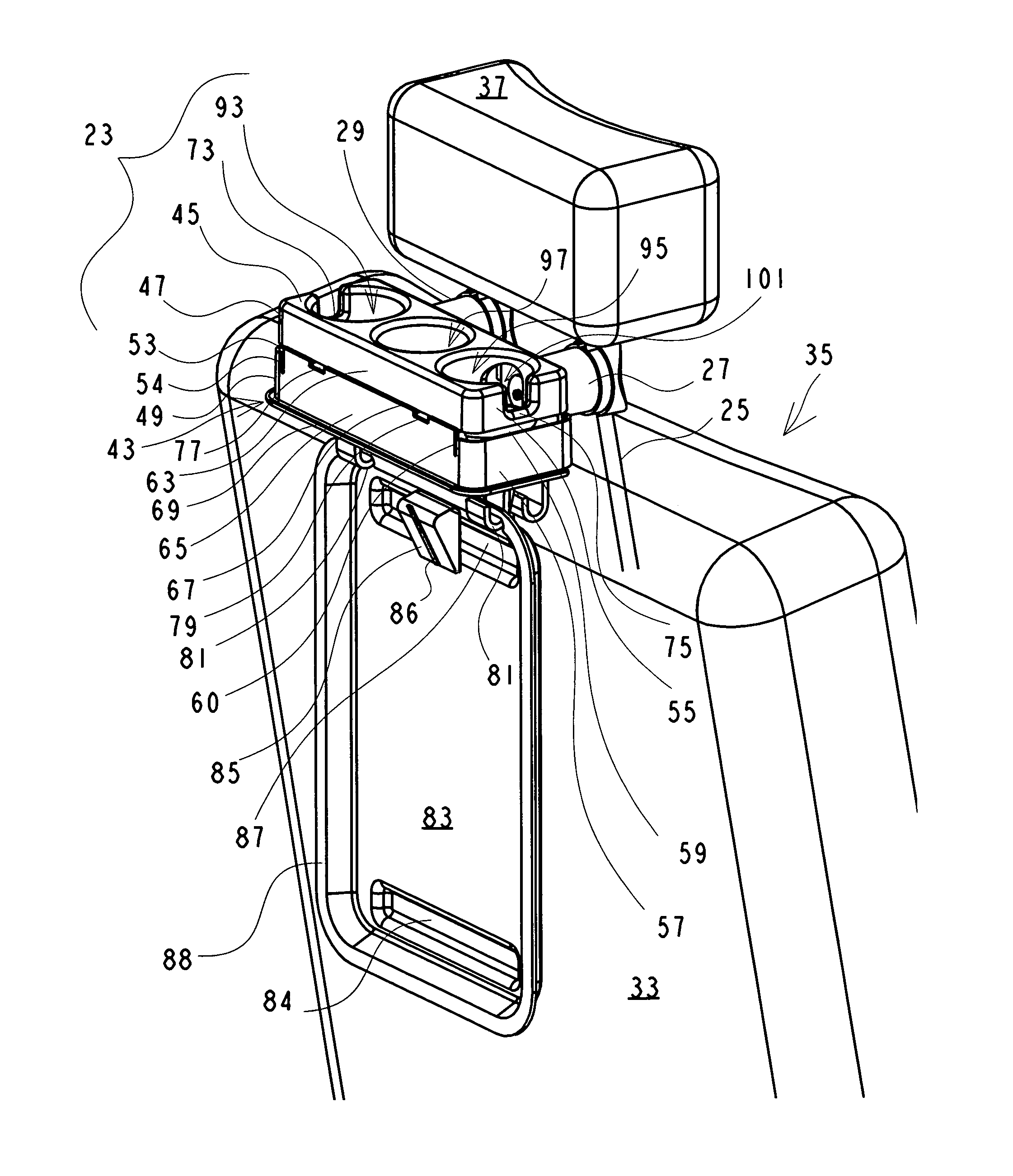
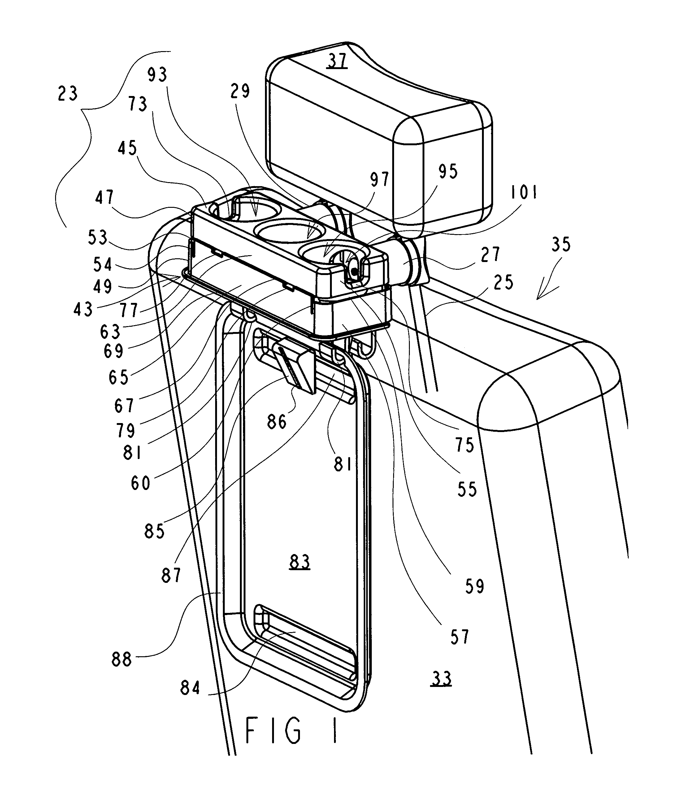
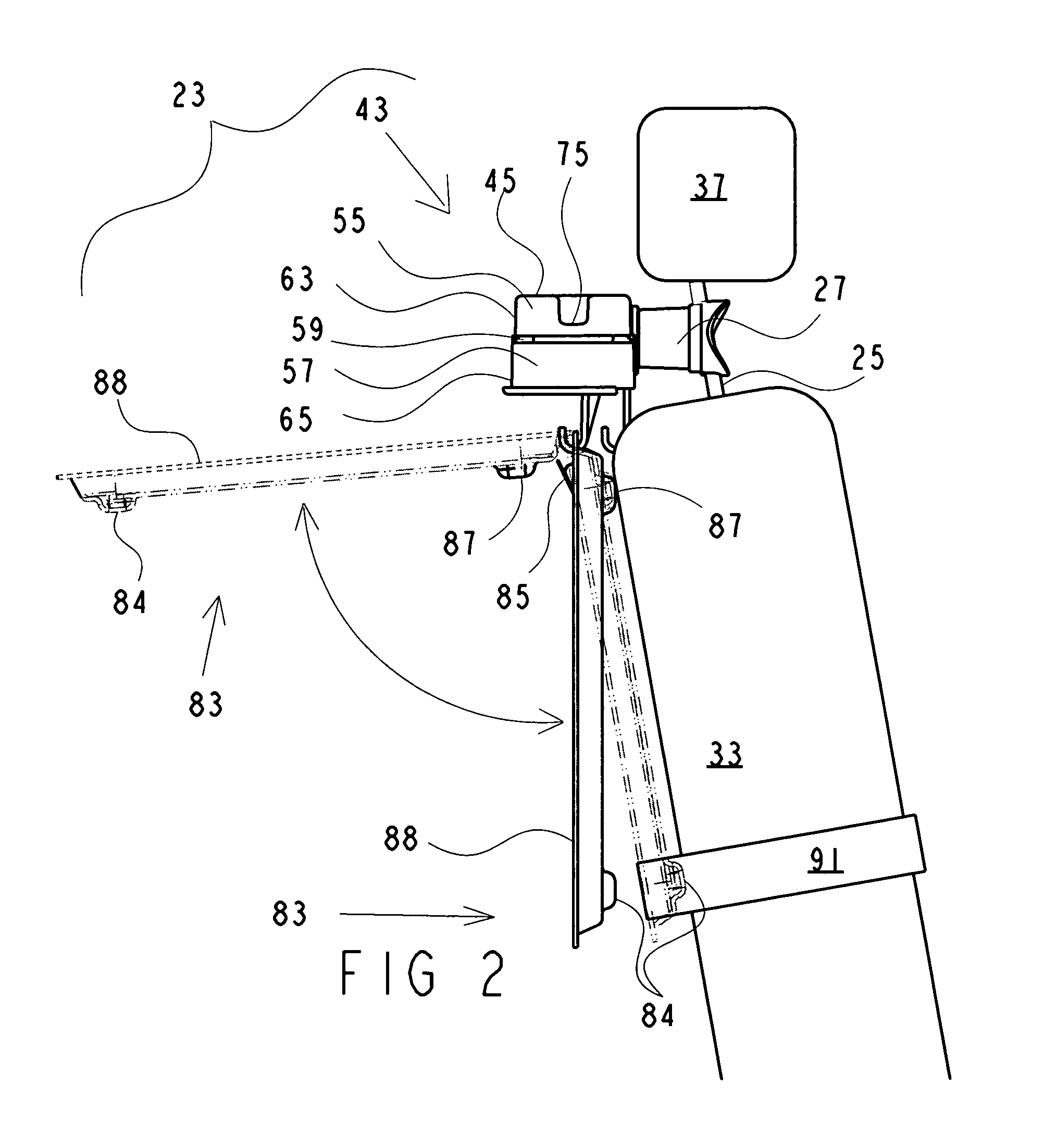
[0036]FIG. 1 is a perspective view of the auto caddy 23 of the present invention which illustrates the auto caddy 23 attached to a pair of headrest seat posts 25 by a first attachment member 27 and a second attachment member 29. Vehicle seat back 33 and headrest 37 are also shown in FIG. 1 for environmental completeness. Auto caddy 23 may include a housing 43 adjacent attachment members 27 and 29. Housing 43 may include a top surface 45, a first upper side wall 47, a first lower side wall 49, a first side slot 53 extending between first upper and lower side walls 47 and 49 and including a first front terminus 54, a second upper side wall 55, a second lower side wall 57, a second side slot 59 extending between second upper and lower side walls 55 and 57 and including a second front termin...


PUM


Abstract

The auto caddy of the present invention may include a main housing having one or more receptacles for holding drinks or other items, and may include one or more attachment members having one or more sets of openings through which a vehicle headrest seat post may extend on installation with two points of contact, which may increase the stability of the auto caddy, especially during sudden movement of a vehicle. The auto caddy may include optional components for subdividing receptacles, one or more hooks from which a tray may be suspended, a strap for securing the tray, and slots for suspending a trash receptacle such as a plastic grocery bag. The auto caddy may also include offset sides for manufacturing cost efficiency, in which case offset washers (which may be hook-shaped) may be used at installation to maximize vertical and horizontal alignment and stability of the auto caddy.

Description

FIELD OF THE INVENTION[0001]The present invention relates to the field of automobile caddies, and more particularly to a multi-purpose automobile caddy which may be stably mounted so that it may be used in a vehicle, and more particularly may be safely used in a moving vehicle as an organizer, a cupholder, an eating and / or working surface, and / or a trash receptacle holder.BACKGROUND OF THE INVENTION[0002]Although auto caddies are well known and widely available, few, if any, offer a high degree of functionality in combination with secure, highly stable installation and safe operation. One of the more well-known conventionally available auto caddies is designed to sit on an auto seat, in either the front or rear of a vehicle. The middle seatbelt is generally used to restrict movement of this type of caddy during stops and starts, sharp turns, and other sudden vehicular movements. Typically, however, large drinks or top-heavy items housed in this kind of caddy may be easily dislodged ...

Claims


Application Information

Patent Timeline
Patent Type & Authority Patents(United States)
IPC IPC(8): B60R7/00A47C7/62
CPCB60N3/004B60N3/103B60R7/043
Inventor SINGH, NEERAJ
Owner SINGH NEERAJ
Learn More