CO2 recovering apparatus

a technology of recovery apparatus and co2 gas, which is applied in the direction of liquid degasification, auxillary pretreatment, separation processes, etc., can solve the problems of catalyst deterioration, facility cost and energy reduction, and the corrosion of the facility, so as to achieve the effect of suppressing air bubbles

Inactive Publication Date: 2013-03-19
MITSUBISHI HEAVY IND LTD +1
View PDF24 Cites 79 Cited by
  • Summary
  • Abstract
  • Description
  • Claims
  • Application Information

AI Technical Summary

Benefits of technology

[0021]The present invention is invented in consideration of the above. An object of the present invention is to provide a CO2 recovering apparatus that can suppress air bubbles getting caught in CO2 absorbing liquid.

Problems solved by technology

Furthermore, upon injecting CO2 into an oilfield using EOR, oxygen could cause facility corrosion.
Moreover, if oxygen is mixed to CO2 when the recovered CO2 gas is used for chemical applications, a catalyst may get deteriorated.
However, in the oxygen reducing technology according to the Published Japanese Translation of PCT Application No. 2004-524147, a separate reducing apparatus such as a flash tank or a vacuum pump is required, thus further requiring facility cost and reduction energy, resulting in a cost increase.

Method used


Image

  • CO2 recovering apparatus
  • CO2 recovering apparatus
  • CO2 recovering apparatus

Examples


first embodiment

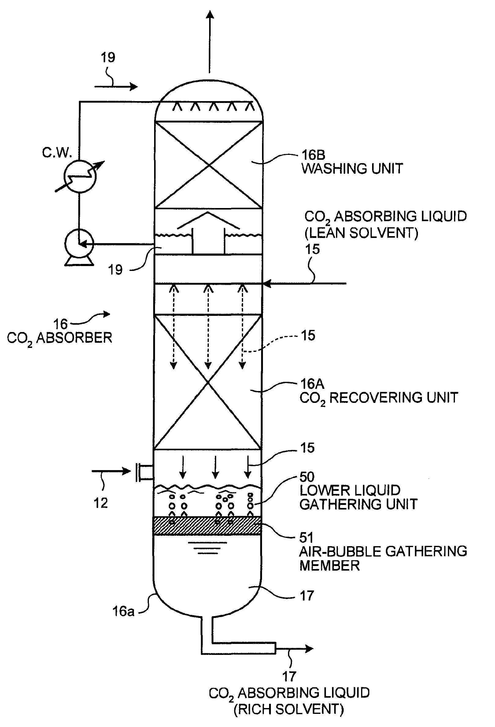
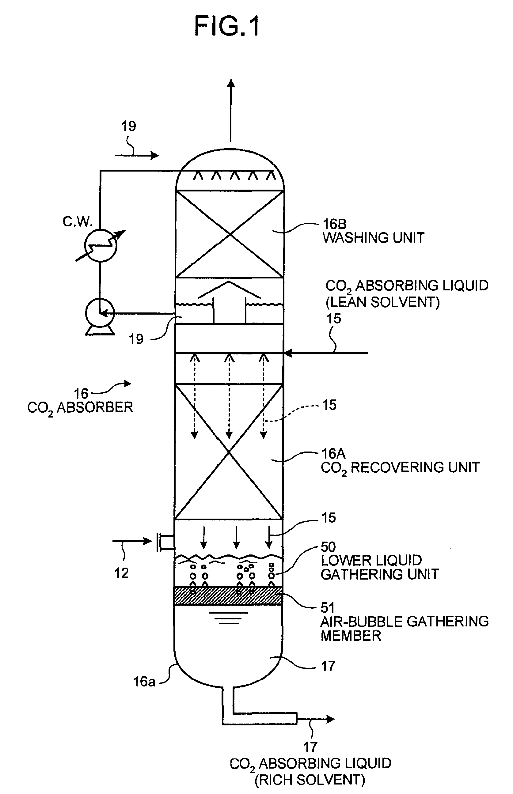
[0028]A CO2 recovering apparatus according to a first embodiment of the present invention will now be explained with reference to FIG. 1.

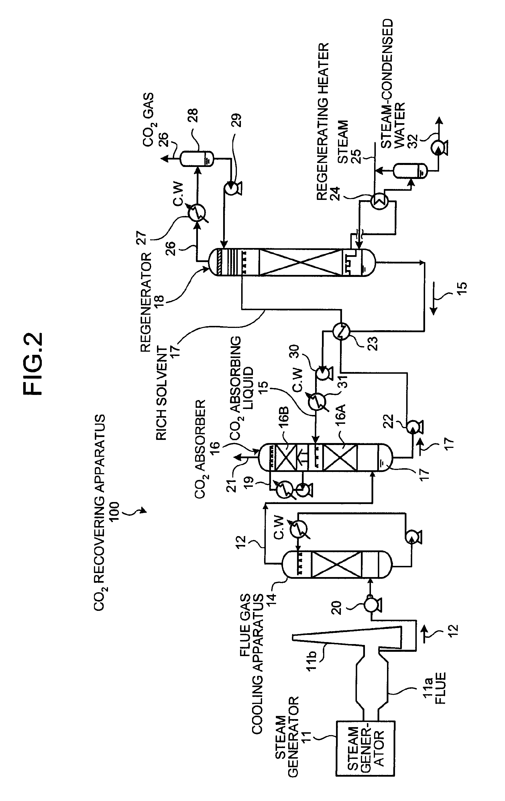
[0029]FIG. 1 is a schematic diagram of a structure of the CO2 recovering apparatus according to the first embodiment. In FIG. 1, the elements same as those in CO2 recovering apparatus shown in FIG. 2 are assigned with the same reference numerals, and redundant explanations thereof are omitted.

[0030]FIG. 1 indicates the CO2 absorber 16 included in the CO2 recovering apparatus 100.

[0031]As shown in FIG. 1, the CO2 recovering apparatus according to the first embodiment includes: the CO2 absorber 16 that brings the flue gas 12 containing CO2 and O2 into contact with the CO2 absorbing liquid (hereinafter, also referred to as “absorbing liquid”) to reduce the CO2 contained in the flue gas 12; a regenerator that reduces CO2 in the CO2 absorbing liquid (hereinafter, also referred to as “rich solvent”) 17 that has absorbed the CO2 in the CO2 absorber 16, an...


PUM

PropertyMeasurementUnit
concentrationaaaaaaaaaa
pressureaaaaaaaaaa
structureaaaaaaaaaa

Abstract

A CO2 recovering apparatus includes a CO2 absorber that brings flue gas containing CO2 and O2 into contact with CO2 absorbing liquid to reduce CO2 in the flue gas; and a regenerator that reduces CO2 in CO2 absorbing liquid (rich solvent) that absorbed CO2 in the CO2 absorber to regenerate the CO2 absorbing liquid, so that the regenerated CO2 absorbing liquid (lean solvent) having CO2 reduced in the regenerator is reused in the CO2 absorber. A lower liquid reservoir is located at the bottom of the CO2 absorber, and an air-bubble gathering member is arranged therein to gather air bubbles included in the absorbing liquid.

Description

BACKGROUND OF THE INVENTION[0001]1. Field of the Invention[0002]The present invention relates to a CO2 recovering apparatus for reducing an amount of O2 accompanying oxygen absorbing liquid, and reducing the concentration of oxygen contained in the CO2 gas regenerated in a regenerator.[0003]2. Description of the Related Art[0004]It has come to be pointed out that one of the causes of the global warming is a greenhouse effect of CO2, and it has became an urgent task, also internationally, to provide a countermeasure for CO2 to protect the global environment against the warming. CO2 is generated by any human activities combusting fossil fuels, and there are increasing demands for suppressing CO2 emissions. Along with such an increasing demand, researchers are energetically investigating a method for reducing and recovering CO2 included in flue gas, to apply in a power plant that consumes a large amount of fossil fuels, such as a thermal plant. In such a method, flue gas emitted from a...

Claims


Application Information

Patent Timeline
Patent Type & Authority Patents(United States)
IPC IPC(8): B01D53/14C01B32/50
CPCB01D53/18B01D53/1475B01D2257/504B01D2256/22Y02C10/06Y02E20/32Y02C20/40
Inventor IIJIMA, MASAKITATSUMI, MASAHIKOYAGI, YASUYUKIOGURA, KOUKI
Owner MITSUBISHI HEAVY IND LTD
Why Eureka
Try Eureka