Device for reading radio frequency identifiers for volumetric confining of the detection region

a radio frequency identification and volumetric confinement technology, applied in the field of devices for ensuring can solve the problems of additional adapting circuitry, difficult to ensure sectored readings of tagged objects, and inability to ensure the volumetric confinement of the detection region, etc., to achieve easy embedding or attaching, simple manufacturing process, and low inherent cost

Active Publication Date: 2013-03-19
INST SUPERIOR TECH +2
View PDF9 Cites 5 Cited by
  • Summary
  • Abstract
  • Description
  • Claims
  • Application Information

AI Technical Summary

Benefits of technology

[0019]The dimensioning previously mentioned, concerning the width of the transmission line, its length and the dimension of the reference ground plane, ensures coverage within a desired detection volume delimited above the reading. Thus avoiding fortuitous detection of RFID tags in the adjacent volumes without the need for metal or absorbing plane barriers to force isolation.
[0020]The present invention is based on a transmission line with a reference metal plane (microstrip line), which leaks from the edges a small fraction of the energy carried from the feeding point to the terminal load. The manufacturing process is very simple and its inherent costs are very low. The invention can be easily embedded or attached to existing structures, for example shelves, tables or conveyor belts.

Problems solved by technology

Presently, RFID reader solutions for RF identification in the UHF band are mostly based on antennas, which alone, do not ensure volumetric confinement of the detection region.
In the UHF and microwave bands, localized antennas are used to produce relatively extensive coverage areas, but it is difficult to ensure sectored readings of tagged objects such as those needed for example to detect objects contained in a small detection volume, while avoiding detection of objects located in areas adjacent to the desired detection volume.
For example, a system consisting of two coplanar transmission lines ensures detection of RFID tags in the region corresponding to the interval between the two lines, U.S. Pat. No. 7,059,518, entitled “RFID Device Detection System and Method.” However, this type of solutions usually requires additional adapting circuitry and does not ensures detection of the tags above its whole surface.
Especially for the higher RFID frequency bands, readjusting of the co-planar lines parameters may not be sufficient to ensure the lateral volumetric confinement of the radiated field; to avoid the detection of labels outside the desired detection volume, additional metal plans barriers may be required.
However, this patent does not specify any type or configuration for the antennas arranged along the tape, or looks for the individual volumetric confinement of the electromagnetic field in each shelf to prevent the reading of books on the adjacent shelves.
The antennas mentioned above, or structures derived by frequency or size scaling, do not allow UHF RFID tag reading for tags transversal to the line which extends to entire length of the reading surface.
Nor cumulatively ensure a confined detection of multiple tags within a desired detection volume above the reading surface.

Method used


Image

  • Device for reading radio frequency identifiers for volumetric confining of the detection region
  • Device for reading radio frequency identifiers for volumetric confining of the detection region
  • Device for reading radio frequency identifiers for volumetric confining of the detection region

Examples


example 2

Conveyor Belts

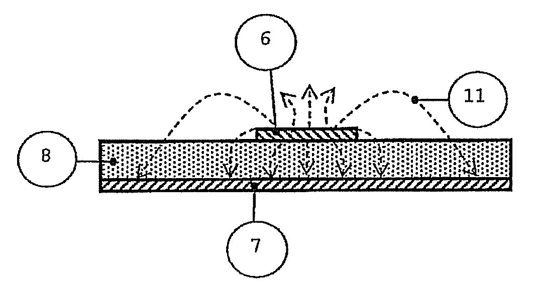
[0046]Another embodiment of the present invention is a conveyor belt. As the meandered curvature of the transmission line 6 in the device 1 is increased, the maximum vertical detection range for RFID tags 13 increases. However, the coverage is reduced in depth in certain areas of the device 1, but the field intensity above the transmission line 6 is similar in all directions. This feature allows the applicability of the invention, for example, in conveyor belts 21 for objects 2 transportation in supermarket payment terminals or warehouses, as shown in FIG. 6. With the movement 20 of the conveyor belt 21, the objects 2 placed above it sweep along the device that is fixed and mounted beneath the rotating belt. For such applications, it is not necessary that the device 1 extends along the entire length of the conveyor belt 21, it is only necessary that the object 2 sweeps through a distance equivalent to a period of the curvilinear line 6, if it is periodic. Thus, detecti...

example 3

Point Readers and Payment Terminals

[0047]A third and fourth embodiments of the present invention are point reader and payment terminals. As previously mentioned, the length of the invention is not a restriction to its implementation and therefore smaller embodiments, similar to the existing terminals for reading bar codes, are foreseen. One example is the RFID point reader 23, arranged in several areas in shops or in payment terminals 22, as shown in FIG. 7a and FIG. 7b, respectively. The choice of the configuration for the transmission line 6 of the device 1 depends on the desired range and on the orientation of the RFID tags 13 on the objects 2 to be identified. The fields volumetric confinement of the device 1 is provided by the transmission lines 6 with total length next or superior to the wavelength at UHF. Unlike optical bar code reader, the RFID point reader 22 and 23 do not require line of sight with the RFID tags 13 and allows simultaneous detection of all products 2 in the...


PUM


Abstract

Device for reading radio frequency identifiers (RFID) ensuring volumetric confinement at UHF of the detection of RFID tags to a desired volume above a reading surface, which includes one or more metallic transmission lines (6) printed on a dielectric substrate (8), on a metallic reference ground plane (7), an RFID reader or interrogator (3) at one end and a load (10) at the other end whereby a structure (19,21,22,23), that comprises the reading surface, in which the one or more transmission lines (6), the dielectric substrate (8) and the metallic reference ground plane (7) are embedded or attached, and the electric fields (11) are contained in planes perpendicular to the one or more transmission lines (6) with one to five wavelengths that extend over all or part of the length of the reading surface, and wherein the dielectric substrate (8) has a low permittivity, less than 1.5 and the width of the transmission line (6) is comprised between 8 and 15% of the wavelength.

Description

FIELD OF INVENTION[0001]The present invention relates to radio frequency identification (RFID) systems. More particularly, the invention relates to devices for reading radio frequency identifiers while ensuring a volumetric confinement of the detection region to a desired volume above the reading surface of the device.STATE OF THE ART[0002]Radiofrequency identification (RFID) technology allows wireless reading and detection of RFID tags, without requiring line of sight. Each RFID tag is associated with a unique code, so that its placement on an object allows a distinctive remote identification.[0003]A conventional RFID system includes RFID tags and one or more reader antennas connected to a radiofrequency reader or interrogator. RFID tags, which consist on a chip and an antenna, can belong to different classes depending on its operation mode: passive tags, active and semi-passive. Active RFID tags include their own power source (typically batteries) and transmit the signal to the re...

Claims


Application Information

Patent Timeline
Patent Type & Authority Patents(United States)
IPC IPC(8): H04Q5/22
CPCG06K7/0008G06K7/10316G06K7/10346H01Q1/2216H01Q13/206
Inventor DOS REIS MEDEIROS, CARLA SOFIALOPES LEAL RODRIGUES DA COSTA, JORGE MANUELCARDOSO FERNANDES, CARLOS ANTONIO
Owner INST SUPERIOR TECH
Why Eureka
Try Eureka