Check patentability & draft patents in minutes with Patsnap Eureka AI!

In place line splitting process and method for multiple beam printers

a printer engine and in-place line technology, applied in the field of methods or processes, computer readable media, image forming apparatus, etc., can solve the problems of limited memory system of the corresponding on board memory system of the lower cost printer and/or multi-functional peripheral, and the cost of microprocessors with more memory is more expensive than those with less memory

Active Publication Date: 2013-03-19
KONICA MINOLTA LAB U S A INC
View PDF6 Cites 0 Cited by
  • Summary
  • Abstract
  • Description
  • Claims
  • Application Information

AI Technical Summary

Benefits of technology

The present invention is a new image forming apparatus and method that solves issues with limited memory in multi-beam or dual beam print engines. It improves performance by performing in place line splitting.

Problems solved by technology

It can be appreciated that typically only lower cost printers and / or multi-functional peripherals have a dual beam design, and the corresponding on board memory system for these lower cost printers and / or multi-functional peripherals is also limited.
However, typically, microprocessors with more memory are more costly than those with less memory.

Method used


Image

  • In place line splitting process and method for multiple beam printers
  • In place line splitting process and method for multiple beam printers
  • In place line splitting process and method for multiple beam printers

Examples


Embodiment Construction

[0020]Reference will now be made in detail to the present preferred embodiments of the invention, examples of which are illustrated in the accompanying drawings. Wherever possible, the same reference numbers are used in the drawings and the description to refer to the same or like parts.

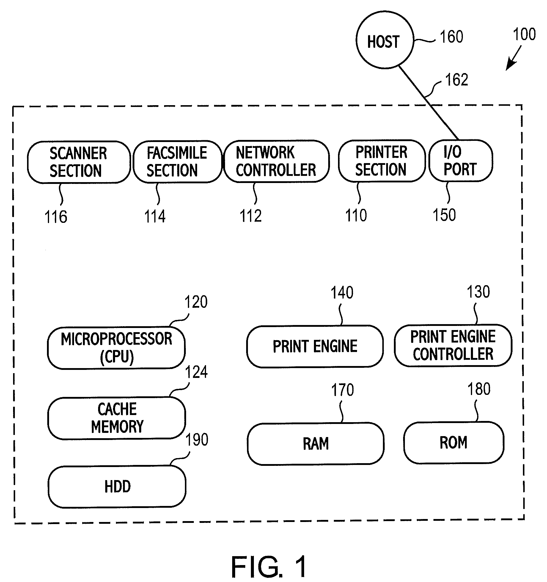
[0021]FIG. 1 is a block diagram showing the configuration of an image forming apparatus 100 for a multi-beam (or multiple beam) laser printer engine 140 in accordance with an exemplary embodiment of the present invention. In accordance with an exemplary embodiment, the image forming apparatus 100 is configured as a multi-functional peripheral (MFP) that has, a scanner section 116 for optically reading a document, a copying section 118 for forming and printing out the corresponding image obtained by the reading onto a sheet, a printing section 110 for converting print data inputted from outside to image data and forming and printing out the converted image onto a sheet, a facsimile section 114 for fac...


PUM


Abstract

A method of rasterizing a print image plane for a multiple beam printer engine, which comprises the steps of receiving an image having a plurality of lines of print data for processing by the printer engine, and performing a print image plane rasterization. The print image plane rasterization includes (a) calculating a first line destination for a first line of print data; (b) moving the first line of print data to the first line destination; and (c) calculating a displaced line destination for a displaced line of print data, and continually moving the displaced line of print data to the displaced line destination until the displaced line of print data is moved to the first line and forms a loop. The process is repeated until each line of the plurality of lines has been moved to a line destination associated with each line of the image.

Description

FIELD OF THE INVENTION[0001]The present invention relates to a method or process, a computer readable medium, and an image forming apparatus, and more particularly to an in place line splitting process and method for a multiple beam printer engine.BACKGROUND OF THE INVENTION[0002]Multi-functional peripherals (MFPs) provide a plurality of functions, such as a printer function, a scanner function, etc., (sometimes referred to herein as an image forming apparatus). Multi-functional peripherals typically include a laser imaging device as the printer function. Efforts are continually being made to increase the printing / copying speed of such devices, while at the same time maintaining quality and reducing their cost.[0003]Laser printers are designed to produce an image on paper or other print material by placing overlapping dots at virtual positions defined by a digital raster. A raster graphic image or bitmap is generally a rectangular grid of pixels, or points of color. These virtual po...

Claims


Application Information

Patent Timeline
Patent Type & Authority Patents(United States)
IPC IPC(8): G06F15/00G06K1/00H04N1/60
CPCG06K15/1863G06K15/1257G06F15/00
Inventor HU, HAO
Owner KONICA MINOLTA LAB U S A INC
Features
  • R&D
  • Intellectual Property
  • Life Sciences
  • Materials
  • Tech Scout
  • Unparalleled Data Quality
  • Higher Quality Content
  • 60% Fewer Hallucinations
Learn More