Display device

a display device and display screen technology, applied in the direction of casings/cabinets/drawers, casings/cabinets/drawers, instruments, etc., can solve the problems of affecting the coupling strength between the elements of the display device, the price of the frame material used for manufacturing the frame also affects the overall production cost of the liquid crystal display, etc., to improve the susceptibility to electromagnetic interference

Active Publication Date: 2013-03-19
AU OPTRONICS CORP
View PDF19 Cites 3 Cited by
  • Summary
  • Abstract
  • Description
  • Claims
  • Application Information

AI Technical Summary

Benefits of technology

[0007]It is an object of the present invention to provide a display device having reduced weight because of using less number of elements.
[0008]It is another object of the present invention to provide a display device with reduced overall thickness.
[0009]It is yet another object of the present invention to provide a display device having a structure with improved resistance toward electromagnetic interference or electrostatic discharge.
[0011]In different embodiments, the display device includes a side frame and a reinforcing rib, wherein the side frame is disposed between the front frame and the main back cover and substantially covers the lateral side of the panel module. The reinforcing rib is preferably disposed at the back side of the panel module. Two ends of the reinforcing rib are preferably connected two opposite sides of the side frame. Furthermore, at least one through hole is formed on the recess portion of the main back cover for a part of the reinforcing rib to pass through and electrically connect with the circuit device. In different embodiments, the reinforcing rib is electrically connected with the circuit device and is used as a ground to improve the susceptibility toward electromagnetic interference and electrostatic discharge of the electrical device and the overall reliability of the display device.

Problems solved by technology

For screw holes formed on the frame will be cancelled and impairing the coupling strength between elements of the display device.
Furthermore, the price of material used for manufacturing frame also affects the overall production cost of liquid crystal display.
Thus one critical issue in reducing the cost of producing liquid crystal display includes manufacturing the frame efficiently based on characteristics and prices of materials.

Method used


Image

  • Display device
  • Display device
  • Display device

Examples


Embodiment Construction

[0019]The present invention provides a display device, wherein the display device described below includes a liquid crystal panel device, but is not limited thereto; in different embodiments, the display device can include an organic light emitting diode panel device. Furthermore, the display device of the present invention includes a front frame, a main back cover, and a sub-back cover.

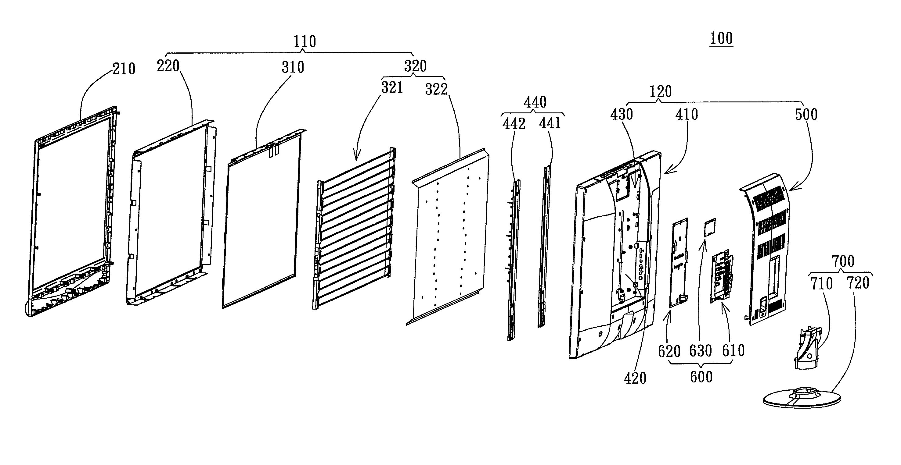
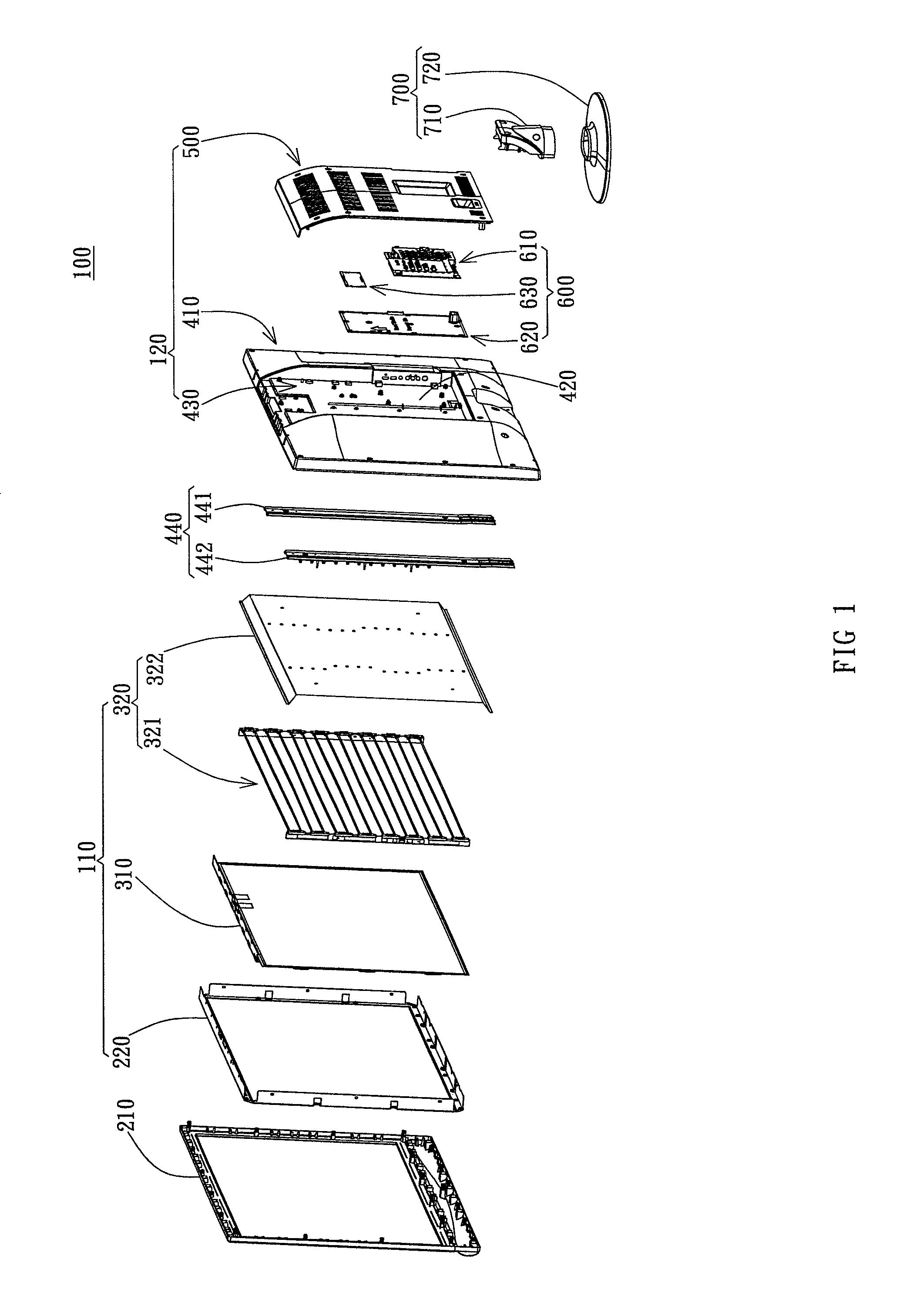
[0020]FIG. 1 is an exploded view of the display device 100 of the present invention. As FIG. 1 shows, the display device 100 includes a panel module 110, a back cover set 120, a front frame 210, a circuit device 600, and a stand set 700. The back cover set 120 includes a main back cover 410 and a sub-back cover 500, wherein the panel module 110 is disposed between the front frame 210 and the main back cover 410. The circuit device 600 is disposed between the main back cover 410 and the sub-back cover 500. The stand set 700 of the present embodiment includes a post 710 and a base 720 respectively, whe...


PUM


Abstract

A display device includes a front frame, a panel module, a main back cover, a sub-back cover, a circuit device and a stand set, wherein the main back cover includes a recess portion sinking from the main back cover toward the panel module. An inner space is formed between the recess portion and the sub-back cover. The circuit device is disposed in the inner space and connected to the recess portion. In different embodiments, the display device includes a reinforcing rib for grounding purpose. The reinforcing rib is disposed on the panel module and is located between the panel module and the main back cover. Furthermore, a through-hole is formed on the recess portion for the reinforcing rib to pass through and electrically couples with the circuit device.

Description

BACKGROUND OF THE INVENTION[0001]1. Field of the Invention[0002]This invention relates to a panel display device; especially to a panel display device having a frame made of different materials.[0003]2. Description of the Prior Art[0004]Since the liquid crystal display has become the mainstream of current flat displays, the reduction in thickness, weight and overall production costs has always been the focus of the manufacturer. The weight reduction focuses on reducing the number of elements used or reducing the weight of element used while maintaining the functionality. One approach to achieve this goal is to reduce the use of non-functional elements.[0005]As for liquid crystal displays, the frame thereof uses most of the non-functional materials and thus the weight reduction of conventional liquid crystal display normally starts from reducing the material of frame used in display. For screw holes formed on the frame will be cancelled and impairing the coupling strength between ele...

Claims


Application Information

Patent Timeline
Patent Type & Authority Patents(United States)
IPC IPC(8): H05K5/00H05K7/00
CPCG02F1/133308H05K5/02G02F2001/133314G02F2001/133334G02F1/133334G02F1/133314
Inventor WANG, CHUNG-MINSHAO, KUAN-CHANGCHEN, CHIEN-FU
Owner AU OPTRONICS CORP
Why Eureka
Try Eureka