
Flow-volume regulator

a flow-rate regulator and flow-rate technology, applied in the field of flow-rate regulators, can solve problems such as impaired function of flow-rate regulators of this type, and achieve the effect of high functional reliability

Active Publication Date: 2013-03-26
NEOPERL
View PDF9 Cites 12 Cited by
  • Summary
  • Abstract
  • Description
  • Claims
  • Application Information

AI Technical Summary

Benefits of technology

The invention is a sanitary insertion cartridge that allows a large amount of fluid to flow through at low pressure conditions while maintaining a constant flow rate of fluid per unit of time at high pressure conditions. This results in a soft water jet that is homogeneous, non-splashing, and optionally sparkling, with high functional reliability and minimal maintenance.

Problems solved by technology

Like jet regulators, flow rate regulators of this type are impaired in their function by the dirt particles entrained in the liquid, which may accumulate before or in the control gap of the flow rate regulator or in the jet divider of the jet regulator.

Method used


Image

  • Flow-volume regulator
  • Flow-volume regulator
  • Flow-volume regulator

Examples


Embodiment Construction

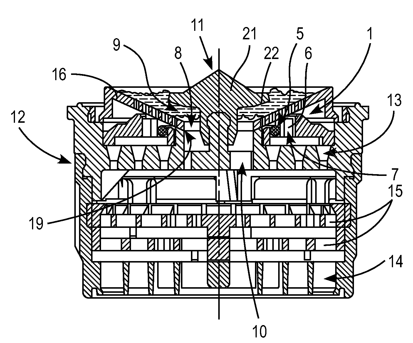
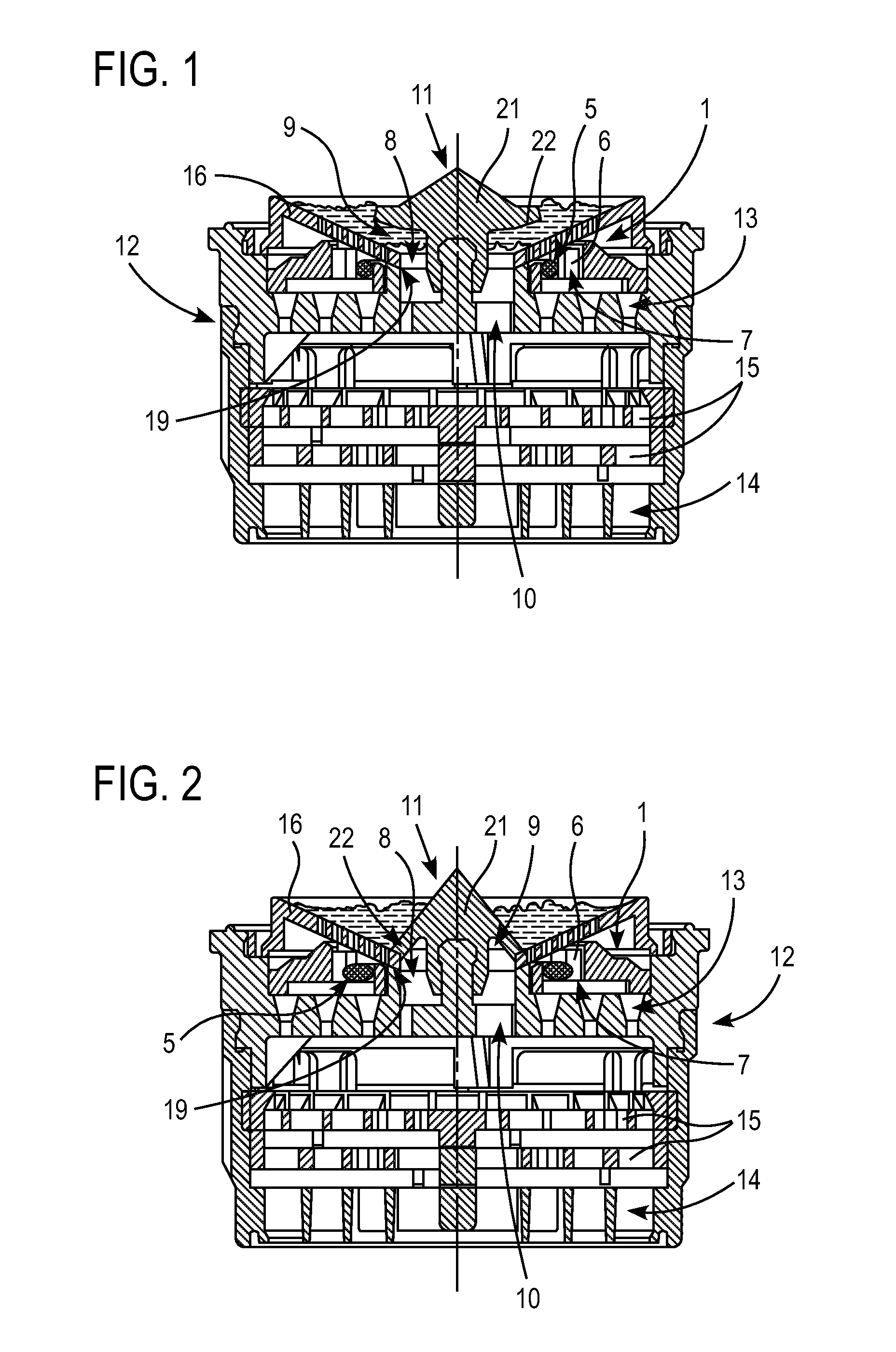
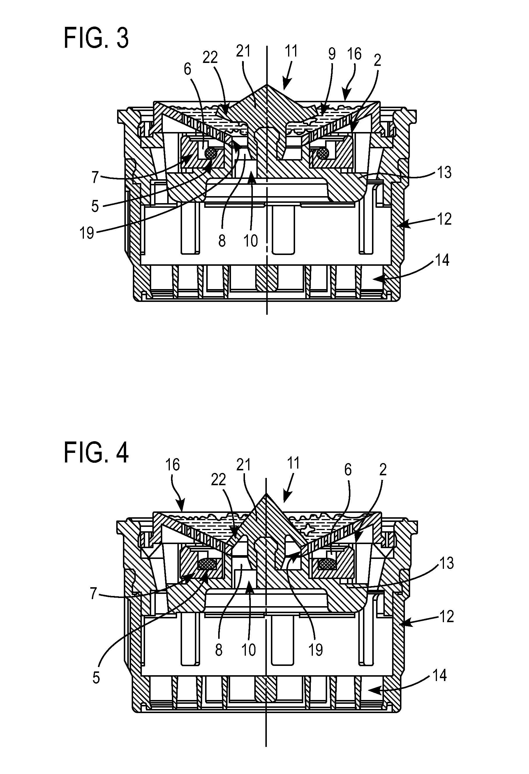
[0030]FIGS. 1 to 6 depict a variety of embodiments of a sanitary insertion cartridge, which is insertable into a sanitary liquid line and has a flow rate regulator 1, 2, or 3, which is arranged between a prefilter or filter screen (16) and a jet regulator (12). The sanitary insertion cartridges can be installed in the outlet orifice of a plumbing outlet fixture (not shown in detail). It is also possible to insert comparable insertion cartridges in a gas or fluid line.

[0031]The flow rate regulators 1, 2, or 3 are designed to adjust the volume of fluid flowing through per unit of time to a fixed maximum value even when the pressure of the inflowing fluid rises. To this end, the flow rate regulators 1, 2, or 3 include an annular restrictor 5, which is made of an elastic material and which delimits a control gap 7 that changes under the pressure of the fluid flowing through, between the restrictor and a wall 6 of the housing. The wall 6 of the housing, which is constructed in FIGS. 1 to...


PUM


Abstract

A flow-volume regulator has an elastic throttle body which delimits, between itself and a housing wall, a control gap that changes under the pressure of a fluid flow, and at least one associated bypass and / or cleaning channel that has at least one channel inlet arranged upstream of the control gap and at least one channel outlet arranged downstream of the control gap. The bypass and / or cleaning channel contains a valve which can move against a restoring force under the pressure of the oncoming fluid, from an open position into a closed position, and seals the bypass and / or cleaning channel in its closed position. The flow-volume regulator allows an additional volume of the fluid through the bypass channel when the oncoming fluid is at low pressure, so that its flow curve is significantly increased in the low pressure range.

Description

[0001]This application is a national stage of PCT International Application No. PCT / EP2007 / 009954, filed Nov. 17, 2007, which claims priority under 35 U.S.C. §119 to German Patent Application No. 20 2006 018 577.1, filed Dec. 6, 2006; No. 10 2006 057.795.7, filed Dec. 6, 2006, No. 10 2007 009 717.6, filed Feb. 28, 2007; and No. 20 2007 002 904.7, filed Feb. 28, 2007, the entire disclosures of which are herein expressly incorporated by reference.[0002]The invention relates to a sanitary insertion cartridge, which is insertable in a sanitary liquid line and has a flow rate regulator with an elastic restrictor which delimits a control gap that changes under the pressure of the fluid flowing through, between itself and a wall of the housing. At least one bypass channel and / or cleaning channel assigned to the flow rate regulator has at least one channel inlet arranged (relative to the flow direction) before the control gap, and at least one channel outlet arranged (relative to the flow d...

Claims


Application Information

Patent Timeline
Patent Type & Authority Patents(United States)
IPC IPC(8): F16K25/00
CPCG05D7/012Y10T137/7785Y10T137/8122Y10T137/2605Y10T137/7504
Inventor ZOLLER, UWE
Owner NEOPERL
Learn More